

Module 4 · Unit 1
Read the unit content below, then use the case studies and key terms to review what you have learned.
By the end of this session, learners should be able to:
A district-heating system distributes thermal energy from one or more sources to several buildings through a network of pipes.
It may supply:
District heating is most viable where there is sufficient heat-demand density, suitable heat sources and a long-term case for shared infrastructure.
District energy systems may also include district cooling.
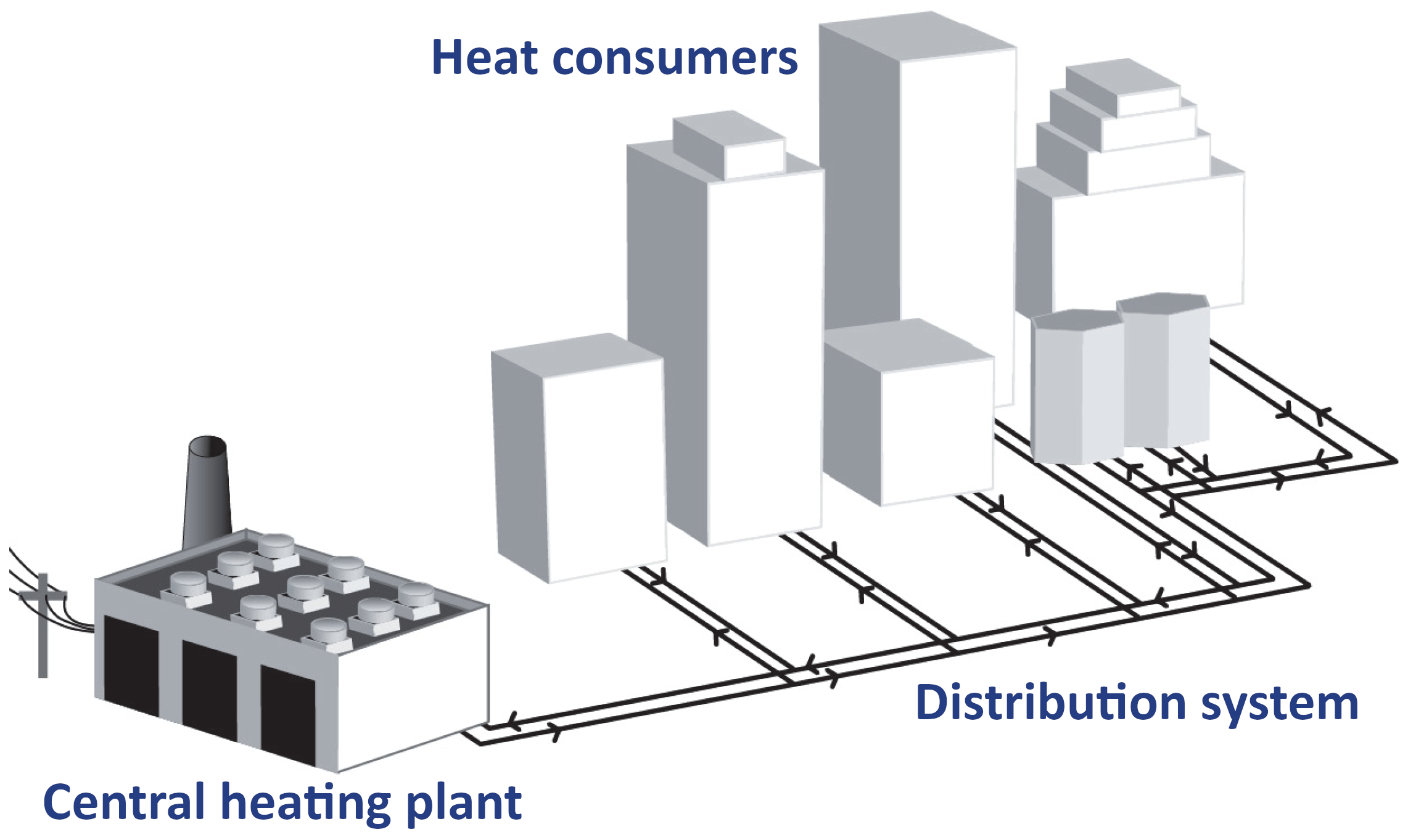
providing approximately 11 – 12 % of the total heat demand.
Some countries don’t have district heating at all,
but some provide more than 50 % of heat energy by this system.
District heating systems are being proposed as the future solution
for urban heating in Europe with high potential to boost
the integration of renewable energy in the heating sector.
Decarbonizing the heating and cooling sector is crucial for advancing the energy transition – a priority recognized by the European Green Deal and the 'Fit for 55' package.
Increasing the share of renewables in this sector is essential to achieving energy and climate targets cost-effectively.
According to the EU Strategy on Heating and Cooling, this involves renovating the existing building stock, improving energy efficiency, and integrating renewable energy sources, supported by decarbonized electricity and district heating.
Heating and cooling can be decarbonised through a combination of:
Lower network temperatures help because they:
1st Generation (1GDH): (1880s – 1930s)
2nd Generation (2GDH): (1930s – 1980s)
3rd Generation (3GDH): (1970s – now)
The generations describe typical system concepts,not mandatory temperature bands or a complete replacement of older systems. Many existing networks still operate with older temperature regimes even if new components are added.
4th generation district heating (4GDH) systems are classified as low-temperature district heating (LTDH) network, operating with heat carrier temperatures below 70 ℃ in the supply pipe and approximately 25 ℃ in the return pipe.
5th generation district heating and cooling (5GDHC) systems are ultra-low temperature district heating (ULTDH) networks, operating at close-to-ground temperatures (< 30 ℃) with distributed heat pumps. Usually capable of providing simultaneous heating and cooling.
5GDH is not a direct continuation of 4GDH but rather a parallel, complementary approach within the broader family of advanced district heating technologies. Some sources recommend using the term “thermal source network” (TSN) rather than “5th-generation district heating” and considers TSNs a subclass of 4GDH networks.
| 4GDH warm network | 5GDHC ambient loop |
|---|---|
| Heat delivered at useful heating temperature | Temperature boosted locally |
| Building heat exchanger commonly used | Building heat pump commonly used |
| Predominantly one-way heat delivery | Potential two-way heat exchange |
| Distribution losses reduced | Distribution gains and losses are comparatively small |
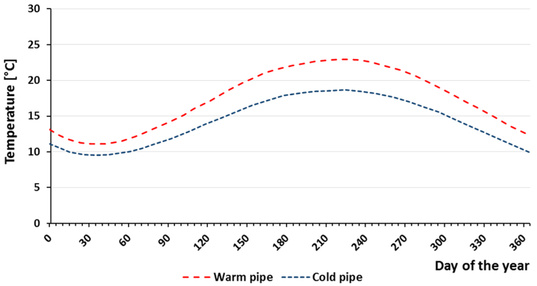
Seasonal temperature variation of the warm and cold pipes in a ground coupled bidirectional 5GDHC system.
Check:
A building that cannot deliver sufficient heat at the lower temperature may require:
The design must maintain:
Possible DHW strategies include:
Lower network temperature is successful only when the complete building system is designed and commissioned for it.
Potential sources include:
Higher-temperature sources
Lower-temperature sources
Heat pumps raise heat from a lower temperature to a useful heating or DHW temperature.
A smaller temperature lift normally improves heat pump COP.
Thermal storage can:
A thermal prosumer can both consume and supply useful thermal energy.
The loop enables energy exchange; long-term storage normally depends on dedicated or environmental storage systems.
A thermal prosumer can both:
Examples include:
The exported heat must meet agreed requirements for:
temperature; flow; availability; control; metering.
A building exporting heat may require:
Heat export or local injection can change hydraulic and temperature conditions of the district heating; the effect must be checked before connection.
Network conditions
Source conditions
A solution that works in one network may not work in another without redesign.
The transition to 4th Generation District Heating (4GDH) and 5th Generation District Heating and Cooling (5GDHC) represents a shift from high-temperature fossil-based systems to low-temperature, decentralized, and flexible networks.
Below are case studies from Denmark, Sweden, and Germany highlighting the technical transitions, building-level implications, and user comfort.
Albertslund, a suburb of Copenhagen, is one of the most prominent examples of a large-scale transition from 2nd/3rd generation (high temperature) to 4th generation (low temperature).
Lund has implemented a massive low-temperature network specifically to utilize low-grade waste heat from the MAX IV laboratory and the ESS research facility.
Germany has been a pioneer in 5GDHC, often called "Anergy" networks, which operate at near-ambient temperatures (5°C to 25°C).
| Feature | 4th Generation (4GDH) | 5th Generation (5GDHC) |
|---|---|---|
| Typical Temp | 50°C – 65°C | 5°C – 25°C (Ambient) |
| Building Hardware | Heat exchangers, low-temp radiators | Decentralized Heat Pumps (per building) |
| Primary Challenge | Building insulation & radiator sizing | High electrical load for HPs |
| Cooling | Possible (separate or absorption) | Inherent (network acts as a sink) |
| User Comfort | Dependent on building envelope | High (Active heating/cooling control) |
Expanding the scope to Norway and the Netherlands provides a look at two different extremes: the conversion of electricity-heavy systems to thermal networks and the use of abandoned industrial infrastructure for 5th generation systems.
Norway is unique because it historically relied on direct electric heating. The transition in Stjørdal represents a strategic shift to free up the power grid.
The "Mijnwater" project in Heerlen is the gold standard for 5th Generation District Heating and Cooling (5GDHC), utilizing flooded coal mines as a thermal reservoir.
| Country | Focus | Key Building Change |
|---|---|---|
| Norway | Grid relief | Install hydronic piping in electric-only buildings. |
| Netherlands | Circularity | Install decentralized heat pumps and bi-directional meters. |
| Denmark | Low-Temp | Upgrade to oversized radiators or floor heating. |
| Germany | Anergy | Integration of 5G "booster" units for domestic hot water. |
These transitions show that while 4GDH focuses on efficiency via lower temperatures, 5GDHC focuses on flexibility via decentralized heat pumps, both of which require buildings to become "active participants" in the energy grid rather than passive consumers.
This case study examines the experience of the Danish city of Albertslund in transitioning to 4th-generation low-temperature district heating (4GDH), and analyses how this practice could be adapted and used in the modernisation of Riga’s heat supply system.
Albertslund’s district heating company was established in 1964. Initially, the system operated with a very high supply temperature of 110 °C (2nd generation). Over the years, as efficiency improved, the temperature was reduced to approximately 90 °C (3rd generation).
To achieve the municipality’s goal of full CO₂ neutrality, the city launched an ambitious transition to a 4th-generation low-temperature network, in which the supply temperature is reduced from 90 °C to 55 °C, while the return temperature reaches approximately 30 °C. After a successful first phase, the municipality decided to fully convert the entire city system, which serves approximately 30,000 residents, by 2026.
Practical solutions that have produced results in Albertslund:
Gradual and phased connection through shunt valves: The new low-temperature loop is supplied using return water from the “old” high-temperature system, which is mixed with the help of a shunt valve to exactly 55 °C. This allows both systems to coexist during the transition period.
Innovative instantaneous water heaters: New compact heat exchangers have been installed in apartments to provide domestic hot water preparation on the consumer side at a temperature of 45 °C.
Legionella control through design: Because the domestic hot water temperature is relatively low (45 °C), there is a Legionella risk. Albertslund solved this by using the German DVGW W55 standard: the volume of water present in the heat exchanger and the domestic hot water system at any one time is so small that the bacteria have neither the time nor the environment to multiply.
Adaptation of end-user systems: After renovation, apartments are heated using optimised radiators and underfloor heating that can operate effectively with a 55 °C supply temperature.
The Albertslund example clearly shows that the transition to low-temperature networks is not merely an engineering repair of the network, but a comprehensive approach. The necessary preconditions are:
Improving the energy efficiency of buildings (insulation): Older, poorly insulated buildings cannot provide the required comfort level at low temperatures. Building renovation is a mandatory precondition.
Synergy between urban planning and utility network development: The transition plan must be precisely aligned with the city’s building renovation programme.
Technological readiness on the user side: It is necessary to replace substations in apartments with modern instantaneous heaters and to adapt heating elements, such as larger radiators or underfloor heating.
Heterogeneity of the building stock: Unlike new districts, where low-temperature networks are easy to introduce, older buildings require substantial capital investment before they can be connected to the new network. Poor insulation means an immediate loss of comfort for residents if the temperature is reduced.
Public resistance and financing: Convincing apartment owners of the need for renovation and replacement of internal substations can be a slow and legally complex process.
Management of the transition period: The system operator must be able to maintain two different operating regimes, high-temperature and low-temperature flows, safely and simultaneously within one city network without causing hydraulic or thermal shocks.
Biological risks: Lowering the domestic hot water temperature to 45 °C increases the risk of Legionella proliferation unless specific engineering solutions are used.
Riga’s heat supply system, which is largely managed by AS “Rīgas Siltums”, has historically been based on high-temperature regimes and includes a large share of unrenovated Soviet-era standard-design apartment buildings. The Albertslund experience offers Riga a direct model for action:
Riga does not need to rebuild its main transmission networks immediately. In districts such as Purvciems, Pļavnieki or Ziepniekkalns, local “low-temperature islands” could be created. In these blocks, the return water from the large main network, usually around 50-60 °C, could be used to supply heat to new or fully renovated buildings. By mixing it with smart shunt valves, the ideal temperature for modernised buildings is obtained, while the overall system is relieved and heat losses in pipelines are dramatically reduced.
At present, the pace of building insulation in Riga is insufficient. Drawing on the Danish example, Riga City Council could combine building insulation projects, such as ALTUM programmes, with the modernisation of the district heating network in a specific block. As soon as 70-80% of the buildings in a block have been insulated, the block is switched to a 55 °C operating regime.
A major challenge in Riga is the internal utility infrastructure. The transition to 45 °C domestic hot water on the consumer side, as in Albertslund, would allow Riga to reduce energy consumption. To prevent Legionella risk in old risers, Riga could adopt the Danish practice: a shift from large domestic hot water storage tanks to ultra-compact instantaneous heat exchangers directly in apartments or at the building inlet, where the water volume is too small for bacteria to multiply.
By reducing the network temperature to 55 °C, “Rīgas Siltums” would be able to integrate large-scale industrial heat pumps into the system much more effectively, for example by using heat from treated wastewater from “Rīgas Ūdens” in Daugavgrīva or surplus heat from data centres, because it is much easier and cheaper for heat pumps to heat water to 55 °C than to the traditional 80-90 °C.
The Albertslund case proves that the transition to low-temperature networks in an existing historic urban environment is realistic and economically justified. For Riga, this would provide:
A reduction in heat losses in transmission networks, which are currently one of the largest cost items.
The possibility of completely phasing out natural gas peak-load stations and replacing them with low-temperature renewable energy sources.
A direct incentive for residents to renovate their homes, because renovated houses will be able to operate in the cheaper low-temperature regime.
Albertslund’s transition to 4th-generation low-temperature district heating (LTDH / 4GDH) is one of Europe’s best-known and most ambitious green transformation projects. Albertslund is a suburb of Copenhagen with approximately 30,000 residents.
This is not a story about building a new, energy-efficient district from scratch. The unique value of Albertslund lies in the fact that modernisation was carried out in an existing, historic urban environment built in the 1960s and 1970s, whose technical challenges are very similar to those of Riga’s residential districts.
A broader and more detailed technical, structural and strategic description of this project is summarised below.
Heat supply has been part of Albertslund’s “DNA” since 1964, when the municipality established its own utility company, Albertslund Forsyning. The system has undergone three major technological leaps:
1960s (2nd generation): The system operated on fuel oil and steam/water, with a supply temperature reaching 110 °C. This caused major heat losses in the pipelines and a high risk of failures.
1980s-1990s (3rd generation): The city connected to Copenhagen’s large transmission network, using surplus heat from a waste incineration plant and combined heat and power (CHP). The network temperature was reduced to 90 °C.
The current project (4th generation): The municipality adopted an ambitious climate plan with the goal of achieving full CO₂ neutrality in heat supply. To achieve this, a plan was created to reduce the network supply temperature fully to 55-60 °C by 2026, and the return flow temperature to 30 °C.
By lowering the temperature by 30 degrees, heat losses in pipelines are reduced by half, or approximately 50%, and the system becomes able to integrate low-temperature renewable resources, such as industrial heat, large heat pumps and solar thermal parks.
The biggest engineering challenge was: how can houses be supplied with a low temperature of 55 °C if the old 90 °C water still comes from the central station?
Albertslund did not dig up all of the city’s main pipelines at once. Instead, it used smart grid division, dividing the city into smaller autonomous blocks and using permanent shunt valves.
[ Central main network: 90 °C supply ] │ ▼[ Shunt unit / valve ] ◄─── (mixed with return water) │ ▼[ Local “low-temperature island”: 55 °C supply ] │ │ ▼ ▼[Building A: renovated] [Building B: new build]
Or, in other words:
[ Central main network: 90 °C supply ] │ ▼[ Shunt unit / valve ] ◄─── (mixed with return water) │ ▼[ Local “low-temperature island”: 55 °C supply ] │ │ ▼ ▼[Building A: renovated] [Building B: new build]
The low-temperature loop, or island, is supplied using return water from the high-temperature system, which is precisely mixed with the help of valves and delivered to consumers as water at 55 °C. Initially, the Danes considered these shunt valves a temporary solution, but practice proved that they are so efficient and flexible that they have now become a permanent part of the network, allowing the city to be switched over gradually block by block.
In order for houses to function with a 55 °C supply temperature, Albertslund simultaneously implemented a large-scale renovation programme for social housing and private homes. For example, in the Albertslund South project, heat consumption fell by 57% after renovation.
Two main elements were installed in apartments and at building inlets:
Direct heating connection: In renovated buildings, underfloor heating and optimised radiators with a slightly larger surface area were installed. These can heat rooms to a comfortable temperature even at such a low water temperature.
Individual apartment substations, or flat stations, with instantaneous heaters: Domestic hot water is not stored in large boilers, where it could cool down and become dangerous. Water is heated at the exact moment the resident opens the tap, reaching 45 °C.
According to general standards, water in a boiler must be above 55 °C in order to destroy Legionella bacteria. In Albertslund, the network temperature is only 55 °C, which means that only 45 °C domestic hot water can be delivered to the consumer. This is an ideal environment for bacteria.
The Danes eliminated this risk by introducing the German safety standard DVGW W55 (small-volume approach). The system is designed so that less than 3 litres of water are present at any one time in the instantaneous heat exchanger and in the pipes up to the tap. The water volume is so small and its circulation so dynamic that the water does not have time to stagnate; bacteria physically have no time to form or multiply.
The project’s success was based on close cooperation with residents. Since 1980, the city has had a User Council with representatives from all residential districts. No strategic decision is approved by the city council without coordination with this council.
To ease the financial burden on residents, because the installation of new substations and meters is expensive, the utility company introduced a new service: rental of smart substations. Consumers did not have to purchase the expensive equipment. The company installed and maintained it for a small fixed monthly fee, while also installing smart meters that analyse data remotely and help optimise consumption.
After several years of operation, including test phases on cold winter days when the outdoor temperature was below zero, the project managers defined four key lessons:
Buildings perform better than expected: The initial engineering calculations were sceptical; it was assumed that old houses would be cold. Practice proved that even partially renovated buildings with LTDH maintain a high level of comfort.
Minimal need for pipe enlargement: The laws of physics state that if the temperature is reduced, the water flow rate must be increased in order to deliver the same amount of energy. There were concerns that pipes would have to be replaced with larger ones. In Albertslund, this was not necessary; the existing network was able to handle the required pressure and flow.
The shunt-valve revolution: Dividing the grid into “islands” proved to be the cheapest and most effective way to modernise the city gradually without stopping or rebuilding the entire system at once.
High consumer support: Residents quickly appreciated the stability and lower bills provided by the new system in combination with building insulation.
This experience serves as a model not only for Riga, but for the entire Baltic Sea region, where historic Soviet-era or post-war networks now require urgent modernisation.
Riga’s path from third-generation district heating to lower-temperature and more flexible heat supply
After studying this material, the reader will be able to explain how Riga’s district heating system can gradually move from a high-temperature third-generation system towards lower-temperature, more efficient and more flexible heat supply, understanding:
why the entire Riga network cannot simply be “switched” to the 4th or 5th generation;
in which districts or projects low-temperature solutions are more credible;
which preconditions must be met on the side of buildings, networks, heat sources and users;
which practical solutions are already being tested or planned in Riga;
which risks must be managed so as not to reduce user comfort.
Riga’s district heating system should currently be regarded as a large, historically developed third-generation system. The existing temperature regime - above 100 °C in winter and approximately 65 °C in summer - shows that the system was designed for high heat-carrier temperatures and for a broad building stock of varying quality.
JSC “Rīgas Siltums” is the largest district heating company in Latvia and the Baltic states and operates as the heat supply operator in the administrative territory of Riga. The company is involved in heat production, transmission, distribution and sales, cogeneration, maintenance of heat networks, and services related to internal building engineering systems.
The total length of Riga’s heat networks in the licensed operating area is approximately 837 km, of which 765 km belong to “Rīgas Siltums”. Of these, 477 km, or 62%, have been reconstructed or newly built, while approximately 300 km still need to be reconstructed. The average age of the networks is 28.4 years, and at least one third of the networks are more than 30 years old.
This means that for Riga the low-temperature transition is not only a technological issue. It is also a programme of network renewal, building renovation, heat-source diversification, market-model development, user comfort and investment planning.
In a large urban system such as Riga, the transition to low-temperature heat supply usually does not happen in a single step. There are several reasons for this.
First, the existing building stock is very diverse. Some buildings have renovated facades, upgraded substations and lower heat consumption, while other buildings still need a higher supply temperature in order to maintain comfort during cold weather.
Second, domestic hot-water preparation is an important limitation. Even if space heating could operate at a lower temperature, domestic hot-water systems must meet hygiene requirements and manage the risk of Legionella.
Third, Riga’s network is not homogeneous. The strategy of “Rīgas Siltums” states that district heating is not available in all city districts, but in the areas where networks are available the customer share is approximately 76%, while in Scandinavia it exceeds 90%. The strategy also emphasises network fragmentation and the existence of separate heat networks on both banks of the Daugava River.
Therefore, the most suitable path for Riga is not the immediate transformation of the entire network into a 4th- or 5th-generation system. A more realistic scenario is:
improving the efficiency of the existing third-generation system;
gradually reducing supply and especially return temperatures;
creating low-temperature zones in new or renovated areas;
integrating waste heat, heat pumps, electric boilers, storage and district cooling;
testing 5th-generation solutions in places where heating and cooling demand exist at the same time.
In 2025, Riga Municipality submitted the “Riga District Heating Development Strategy for 2025-2032” for public consultation. It is a medium-term planning document whose purpose is to define the main directions and measures for heat-supply development in order to achieve climate and energy goals.
Public information about the strategy highlights several directions that are important for Riga: expansion of district-heating zones, attraction of new customers, modernisation of existing infrastructure, construction of new heat-network projects, diversification of heat sources, reduction of dependence on CHPs, and wider use of renewable energy resources.
The medium-term strategy of “Rīgas Siltums” until 2030 explicitly mentions reduced-temperature heat supply as one of the directions for increasing efficiency, because lower temperatures make it possible to reduce heat losses, reduce emissions and use new technologies. The same strategy also mentions district cooling, electric boilers, the Power-to-X approach, waste-heat use, heat pumps and heat storage.
For Riga, a 4th-generation system would not mean one new network across the whole city, but rather lower-temperature zones in which:
buildings are energy-efficient or renovated;
the capacity of radiators, underfloor heating or ventilation heaters is sufficient even at a lower supply temperature;
heating substations are modernised and adjustable;
the return temperature is low;
low-temperature heat sources are nearby;
network hydraulics allow the specific zone to be operated in a separate temperature regime.
In practice, this could mean new or reconstructed neighbourhoods, groups of municipal buildings, industrial zones, development areas around Riga, or individual parts of the city with a good level of renovation.
A 5th-generation system is usually at an even lower temperature, often close to ambient temperature, and has two-way energy flows. Such a system is particularly suitable for places where, within one area, there are simultaneously:
heat demand;
cooling demand;
data centres, offices, retail buildings or production facilities with waste heat;
the possibility of using heat pumps;
new or substantially reconstructed networks.
In Riga, 5th-generation solutions would most likely be suitable not for the direct transformation of the historic high-temperature network, but for new development areas, industrial neighbourhoods, areas around data centres, or district-cooling projects.
| Precondition | What this means for Riga | Practical conclusion |
|---|---|---|
| Building energy efficiency | A lower supply temperature is possible only if the building can provide comfort with lower heat output. | Before reducing the temperature, the building’s heat losses, level of renovation and heating-element capacity must be assessed. |
| Low return temperature | A high return temperature reduces system efficiency and makes it harder to integrate low-temperature sources. | Riga needs a targeted programme for reducing return temperatures. |
| Modern heating substations | Old or poorly adjusted substations may prevent the temperature from being reduced without a fall in comfort. | Adjustable, remotely monitored substations and hydraulic balancing must be introduced. |
| Domestic hot-water solutions | A low temperature for space heating does not mean that domestic hot-water temperature can automatically be reduced. | Safe domestic hot-water preparation solutions must be provided, including local temperature boosting if necessary. |
| Condition of networks | Old networks mean higher losses and a higher risk of failures. | Network reconstruction should be used as an opportunity to prepare zones for lower temperatures. |
| Heat sources | Low-temperature networks make it possible to use waste heat, heat pumps and other low-temperature sources. | Source mapping must be carried out together with network zoning. |
| Economics and tariffs | The transition will be acceptable to users only if it does not increase costs or reduce comfort. | A clear model is needed for investment, tariffs and the distribution of benefits. |
| Regulatory framework | Riga already has territorial requirements for selecting heat-supply solutions and limiting polluting equipment. | Low-temperature development should be linked to air-quality policy and the reduction of polluting heating equipment. |
The air-quality dimension is also particularly important in Riga. In 2023, individual heating was a significant source of particulate pollution: its share was 43% of PM10 emissions and 55% of PM2.5 emissions. The programme document states that the impact of district heating on air quality is considerably smaller than that of individual heating, because large installations allow better combustion control, purification and monitoring.
In its 2024/2025 report, “Rīgas Siltums” states that the largest new-generation, low-potential, or 4th-generation efficient heat network has been completed in Ropaži, connecting 16 residential buildings. New-generation heat networks are also mentioned in A. Čaka Street, K. Barona Street, Mežaparks, Čiekurkalns and the “Domus” project on Kokneses Avenue.
What this teaches Riga: low-temperature solutions are easiest to implement where a new network is built or where an existing zone is substantially reconstructed. This confirms the principle that a 4th-generation system is more often a new or locally reconstructed solution than a simultaneous transformation of the entire historic network.
Practical use in Riga: every new neighbourhood or network reconstruction project should be assessed as an opportunity to create a lower-temperature zone.
“Rīgas Siltums” notes that a 0.30 km long DN80 heat network was built in Žīguru Street, making it possible to eliminate a natural-gas boiler house and connect eight buildings to district heating.
What this teaches Riga: the transition to more sustainable heat supply does not always begin with the 4th or 5th generation. Sometimes the first correct step is to replace polluting or less efficient local boiler houses with a district-heating solution.
Practical use in Riga: areas with local boiler houses or individual heating should be identified where connection to district heating would both reduce emissions and create a future opportunity for low-temperature zoning.
In 2024/2025, “Rīgas Siltums” reconstructed or built 11.05 km of heat networks, including 10.65 km with industrially insulated pipes. The expected reduction in heat losses is 10,373 MWh per year, while the reduction in CO₂ emissions is 1,224 t CO₂e per year.
What this teaches Riga: network renewal is not only a way to reduce the risk of failures. It is also an opportunity to review the temperature regime, hydraulics, connection schemes and future integration of low-temperature sources.
Practical use in Riga: every network reconstruction project should include the question: can this section be prepared for lower-temperature operation in the future?
The strategy of “Rīgas Siltums” states that the use of waste heat in district heating and district cooling with the help of heat pumps could potentially provide up to 25% of the required energy.
Current information for 2024/2025 states that “Rīgas Siltums” and the Riga Energy Agency, within the ENABLE DHC project, are working on the use of wastewater heat recovery from the Daugavgrīva treatment facilities for the heat supply of Daugavgrīva and Bolderāja. Together with Tet, the use of waste heat and cooling is also being assessed for a pilot project.
What this teaches Riga: waste heat and wastewater heat are particularly suitable for lower-temperature systems because they are difficult to use efficiently in a traditional high-temperature network without heat pumps.
Practical use in Riga: planning low-temperature zones should begin with a map of heat sources: wastewater, data centres, industry, retail buildings, cooling systems, and metro or tunnel infrastructure if such infrastructure develops in the future.
“Rīgas Siltums” reports that a 49 MW electrode hot-water boiler has been installed in Imanta, and that absorption heat pumps have been installed in three heating plants to recover heat from flue gases and condensate, reducing the flue-gas temperature to approximately 30 °C.
What this teaches Riga: the transition to next-generation heat supply is not only about lowering the temperature of pipes. It also means a more flexible energy system in which heat supply cooperates with the electricity market, heat storage, heat pumps and waste heat.
Practical use in Riga: lower-temperature networks must be planned together with electricity-system flexibility, heat storage and the use of variable renewable energy resources.
The State Audit Office audit notes that for several years Riga has experienced a situation in which part of the useful heat from Latvenergo CHPs has been released into the atmosphere, while heat has simultaneously been purchased from woodchip boiler houses. The audit states that in the 2024/2025 heating season this resulted in an overpayment of approximately EUR 8 million by heat-energy users.
What this teaches Riga: a technical transition to lower temperatures cannot be successful without improving the heat market, procurement and cooperation model. If waste heat is not used, the system loses both economically and in climate terms.
Practical use in Riga: low-temperature development must be linked to a market model that stimulates the lowest costs, the use of waste heat and the overall efficiency of the system, rather than only the optimisation of individual producers.
A transition suitable for Riga can be structured at four levels.
This is the short- and medium-term foundation. It includes:
heat-network reconstruction;
reduction of heat losses;
reduction of failure risk;
return-temperature control;
modernisation of heating substations;
more accurate data accounting and management;
attracting customers where the network is already available.
The strategy of “Rīgas Siltums” mentions, as one of its goals, increasing customer coverage to 80% in those areas of Riga where district heating is available, as well as developing new services, including the use of return heat and cooling networks.
This level concerns areas where buildings are already sufficiently efficient or where substantial reconstruction is taking place. Practical steps:
select a pilot zone;
check building heat loads;
calculate whether the existing heating elements will work at a lower temperature;
modernise heating substations;
ensure domestic hot-water safety;
reduce the return temperature;
measure comfort and user complaints.
This level is suitable for new development areas, projects around Riga, groups of municipal buildings and neighbourhoods with coordinated planning.
Here the low-temperature principle must be introduced already at the design stage:
low heat load in buildings;
a low-temperature heat source;
carefully designed hydraulics;
heat pumps and storage;
the possibility of connecting cooling or waste heat in the future.
This level is suitable for places with simultaneous heating and cooling needs. In Riga, potentially suitable areas could be:
areas near data centres;
neighbourhoods with office and retail buildings;
industrial areas;
areas around wastewater treatment facilities;
new mixed-use neighbourhoods.
| Risk | How it appears | How to reduce it |
|---|---|---|
| Reduced comfort | Buildings cannot reach the required indoor temperature. | Carry out technical building inspections and pilot measurements before reducing the temperature. |
| High return temperature | Low-temperature sources and heat pumps become less efficient. | Introduce return-temperature monitoring, tariffs or incentives, and heating-substation adjustment. |
| Domestic hot-water safety | Low temperature can create hygiene risks. | Use local temperature boosting, safe heat exchangers and regular control. |
| A pilot that is too broad | If the zone is too complex, the project may fail. | Start with small, technically controllable pilot projects. |
| Distribution of investment | It is not clear who pays for the improvements needed on the building side. | Create a financing model involving the operator, municipality, building owners and support programmes. |
| Mismatch in the market model | Waste heat is not used even when it is technically available. | Improve procurement, data-exchange and cooperation mechanisms. |
| Insufficient customer involvement | Users perceive the transition as a risk rather than a benefit. | Provide clear communication about comfort, costs and benefits. |
In the case of Riga, the main lesson is this: the low-temperature transition is not one large project for the whole city, but a zoned, data-based modernisation programme.
In practical terms this means:
Do not start with the question “how can all of Riga be converted to the 4th generation?” The correct question is: in which zones is it technically, economically and socially possible to reduce the temperature?
First reduce the return temperature. This is one of the most important preparatory steps for any low-temperature strategy.
Use network reconstruction as an opportunity for transition. Every reconstructed section should be assessed not only in terms of failure risk, but also in terms of the future temperature regime.
Start low-temperature zones where three factors coincide: energy-efficient buildings, a suitable heat source and the possibility to separate the network temperature regime.
Do not treat 5th-generation solutions as the next step for all of Riga. They are more suitable for pilot areas with heating and cooling synergy.
Connect local and individual heating facilities where this improves air quality. Riga’s air-quality data show that individual heating is a significant source of fine-particle emissions, so expanding district heating can also be an air-quality instrument.
Treat waste heat as a strategic resource. If Riga wants to move towards lower temperatures, it must learn to use waste heat from wastewater, data centres, industry, cooling and CHPs.
Choose one area of Riga and assess its readiness for low-temperature heat supply.
The following questions should be answered:
What is the current condition and temperature regime of the heat network?
What is the level of building renovation?
Can the existing heating elements in the buildings operate at a lower temperature?
How is domestic hot water prepared?
What is the return temperature?
Are there low-temperature heat sources nearby?
Can the zone be hydraulically separated?
What investments are needed in the network and on the building side?
What are the main comfort, cost and technical risks?
Is the more suitable solution optimisation of the third-generation system, a 4th-generation low-temperature zone, or a 5th-generation pilot?
For Riga, the transition to 4th- and 5th-generation heat supply should not be understood as a rapid abandonment of the existing system. Riga’s practical path is gradual modernisation: network renewal, reduction of return temperatures, attraction of customers, replacement of local polluting heating solutions, use of waste heat, and creation of low-temperature zones where technical and economic conditions allow it.
This approach makes it possible to maintain user comfort, reduce heat losses, improve air quality and at the same time prepare the city for next-generation heating and cooling solutions.
A system that distributes thermal energy, normally through a network of pipes carrying hot water, from one or more central or decentralized heat sources to multiple buildings or sites for space heating, domestic hot water, and sometimes process heat. The system may include production units, recovered heat sources, thermal storage, pumping stations, distribution networks, substations, metering, and controls. Steam is mainly associated with older or specialized networks; low-temperature district heating uses liquid water.
The distribution of chilled water or another cold carrier from one or more centralized or decentralized sources through a network to multiple buildings or sites for space or process cooling. It may use chillers, free cooling, thermal storage, recovered cooling, or reversible heat-pump systems.
The supply or forward-flow temperature is the temperature of network water delivered from the heat source or main network toward consumers; the return temperature is the temperature of water flowing back after heat has been transferred. The temperature difference, ΔT = Tsupply − Treturn, determines the mass flow required for a given heat load. Lower supply temperatures reduce distribution losses, while low return temperatures improve network capacity and the efficiency of many heat sources. A small ΔT increases flow and pumping demand and may limit network capacity.
Thermal energy transferred between the network fluid and the surrounding soil, air, structures, or service spaces during distribution. In warm district-heating networks this transfer is normally a heat loss, and lower supply and return temperatures generally reduce it. In near-ambient thermal source networks (TSNs), the network may either lose or gain heat from the ground, and some designs intentionally use the buried network as part of the environmental heat exchange. Thermal exchange should be distinguished from pumping electricity and conversion losses.
An insulation class describes the thermal-insulation level of a pre-insulated district-heating pipe system. A twin pipe contains both the supply and return carrier pipes within one common insulation layer and outer casing; it can reduce trench width and, in suitable applications, distribution heat loss compared with two separate single pipes. Conventional low-temperature and 4GDH networks generally still use pre-insulated pipes. Near-ambient TSNs may use uninsulated polymer pipes where temperatures, soil interaction, condensation/frost risk, and economics justify that choice.
The interface between the district network and a building or local secondary system. A conventional indirect district-heating substation typically contains a heat exchanger, control valves, metering, sensors, and sometimes pumps or storage, transferring heat without mixing district and building fluids. Direct hydraulic connections also exist. In a thermal source network, the energy transfer station usually includes a reversible water-source heat pump and may also contain heat exchangers, free-cooling equipment, domestic-hot-water equipment, controls, and metering.
A measure of useful heat or cooling demand relative to an area or network length. High demand density often improves district-network economics by increasing delivered energy per meter of pipe, but near-ambient networks may have different feasibility thresholds because pipe cost, heat loss, heat exchange, and customer equipment differ from conventional district heating.
The physical connectivity of pipes, nodes, sources, storage units, and consumers. A branched or radial network has tree-like connections; a ring provides an alternative path around a loop; and a mesh contains multiple interconnected paths. The appropriate topology depends on demand density, source locations, hydraulic control, redundancy requirements, construction phasing, land constraints, and life-cycle cost.
Hydraulic balancing ensures that each branch and customer receives the required flow without excessive differential pressure or bypassing. Pumping energy depends on flow, pressure drop, control strategy, pipe dimensions, and ΔT; it becomes important when low temperature differences require high mass flow.
An approach that reduces network temperatures compared with conventional systems and coordinates network design, heat sources, substations, and building emitters to operate efficiently at those temperatures. Temperature thresholds vary by source; IEA DHC publications describe supply temperatures around 50 °C or below for LTDH, while the simplified generation classification places 4GDH networks at or below 70 °C.
A low-temperature network operated at a temperature too low to meet all building heat demands directly, so local heat pumps or boosters are used for at least some services. The term overlaps with cold district heating, ambient loops, and thermal source networks; the exact temperature boundary must be defined in each study.
A system concept for supplying buildings through hot-water district-heating networks operated at lower temperatures than earlier generations, while coordinating energy-efficient buildings, low return temperatures, renewable and recovered heat sources, thermal storage, smart control, and interaction with the wider energy system. For a simplified temperature-based classification, commonly defined as a system with a maximum forward-flow temperature at or below 70 °C.
A commonly used term for a shared near-ambient-temperature water or brine network that serves as a distributed heat source and heat sink for building-level reversible heat pumps. Connected buildings may extract heat for space heating and domestic hot water, reject heat while cooling, or do both at different times. External heat sources, heat sinks, and thermal storage are used to keep the network within an acceptable operating-temperature band. Project temperatures vary with climate and design; a range such as approximately 5–30 °C is descriptive, not a universal definition. IEA DHC now recommends “thermal source network” rather than “5th-generation district heating” and considers TSNs a subclass of 4GDH networks.
A system designed to match the thermodynamic quality of an energy source to the quality required by the end use. Exergy represents the maximum useful work obtainable as a system comes into equilibrium with its environment. Low-exergy design therefore avoids using high-temperature or otherwise high-quality energy where low-temperature heat is sufficient, and seeks to minimize exergy destruction across generation, distribution, heat pumps, heat exchangers, storage, and building systems.
A shared water or water–glycol network operated within a controlled temperature band close to ambient or ground temperature. It acts as a common heat source and heat sink for connected heat pumps and may exchange energy with the ground, groundwater, surface water, air, thermal storage, or recovered heat sources. Depending on network and soil temperatures, buried pipes may lose heat to or gain heat from the ground.
A heat pump located at a building, cluster of buildings, or local substation. In ultra-low-temperature networks and TSNs, it extracts heat from the shared loop and upgrades that heat to the temperature required by the building’s space-heating or domestic-hot-water system. In reversible operation it can provide cooling and reject heat to the shared loop. Decentralized heat pumps are characteristic of TSNs and some ultra-low-temperature concepts, but they are not required in every 4GDH system.
A heat pump used to raise the temperature of heat taken from a low-temperature network to the temperature required by a particular end use, such as domestic hot water or a higher-temperature radiator circuit. A booster heat pump is commonly located in a building or substation, although the term can also be used for a neighbourhood or central unit; the location and system boundary should therefore be stated.
COP is the ratio of useful heating output to electrical input at a specified operating point. SPF is the same ratio integrated over a season or year and should include clearly stated auxiliaries and system boundaries. In TSNs, heat-pump COP is strongly affected by network temperature and the required temperature lift.
The difference between the heat-source temperature and the required heat-sink or delivery temperature across a heat pump. A smaller temperature lift generally improves COP, although actual performance also depends on equipment, part-load operation, and approach temperatures in heat exchangers.
An operating and market concept in which a connected user may both consume thermal energy and supply usable heat or cold to the network. A prosumer may, for example, inject recovered heat from cooling, refrigeration, a data centre, solar thermal collectors, or a local heat pump. Injection is subject to temperature, hydraulic, water-quality, metering, control, and contractual requirements. Bidirectional thermal exchange does not necessarily mean that mass flow reverses in every pipe.
A mode in which heating and cooling demands occur at the same time and heat rejected by cooling users is recovered through the network to help supply heating users. In near-ambient networks this exchange is usually mediated by the shared loop and reversible heat pumps. It can reduce the net heat that must be supplied from external sources and the net heat that must be rejected to external sinks.
The capture and useful reuse of thermal energy that is not the primary product of a process and would otherwise be rejected to air or water. Sources include industrial processes, data centers, refrigeration systems, wastewater, or power-generation processes. Connection may require a heat exchanger, water-quality separation, thermal storage, and/or a heat pump to reach the required temperature. Feasibility depends on temperature, quantity, load profile, continuity, distance, contamination risk, ownership, long-term availability.
The ability of a district heating and cooling system to use a portfolio of renewable heat and cold sources, recovered excess heat, ambient heat, and electricity-driven heat pumps. Relevant sources include solar thermal energy, geothermal energy, sustainable bioenergy, wastewater and surface-water heat, industrial excess heat, refrigeration heat, and ambient air or ground heat accessed by heat pumps.
The temporary storage of sensible or latent heat or cold for later use. Short-term storage balances hourly or daily mismatches and reduces peak capacity, while seasonal storage shifts thermal energy across weeks or seasons. Technologies include water tanks, pit thermal energy storage, phase-change storage, borehole fields, aquifers, mine water, and building thermal mass. Storage can improve source utilization, heat-pump operation, renewable integration, resilience, and network control.
BTES is a closed-loop underground storage system in which heat-transfer fluid circulates through a field of borehole heat exchangers and stores heat or cold in the surrounding soil or rock. ATES is generally an open-well system that stores and recovers heat or cold using groundwater in a suitable aquifer, commonly through warm and cold wells. Both technologies can provide seasonal balancing and can support 4GDH, district cooling, or TSNs.
The balance over time between heat extracted from and rejected to a near-ambient network, including exchanges with external sources, sinks, storage, and the ground. Persistent annual imbalance can cause long-term temperature drift and reduce heat-pump performance or system capacity.
A thermal network that uses sensors, metering, communication, forecasting, optimization, and automated control to coordinate heat and cold sources, storage, pumps, network temperatures, flow rates, demand response, and customer substations. Smart operation may also coordinate the thermal system with electricity, gas, transport, and industrial energy systems.
A condition in which the measured temperature difference between supply and return is lower than intended because of poor control, oversized or bypassed equipment, excessive flow, fouled heat exchangers, or unsuitable customer systems. It increases pumping demand, reduces network capacity, and raises return temperature in warm district-heating networks.
Legionella risk concerns the potable domestic-hot-water system, not the closed district-heating or ambient-loop fluid. Risk management depends on the system configuration, water temperature and residence time, stagnation, storage volume, circulation, cleanliness, commissioning, and the vulnerability of users. Low-temperature networks may require local temperature boosting, instantaneous domestic-hot-water preparation, very small water volumes, periodic thermal disinfection, or another approved control method. The applicable temperature–time regime must follow local legislation and building-water hygiene guidance.
The ratio of the discounted lifetime costs of a defined heating or cooling system to the discounted quantity of useful heat or cooling delivered over the same analysis period and system boundary. Costs may include capital investment, financing, replacement, operation and maintenance, fuel and electricity, pumping, water treatment, decommissioning, and residual value. Results must state the discount rate, lifetime, price assumptions, utilization, system boundary, and whether network and customer-side equipment are included.
The practice-question document includes answers and explanations for self-study.
When you are ready, take the Unit 1 quiz.