

Module 4 · Unit 2
Read the unit content below, then use the case studies and key terms to review what you have learned.
By the end of this session, learners should be able to:
Heat network
Energy centre
& district pipework
Building substation
Building connection / hydraulic interface
Communal distribution
Risers / laterals
inside building
Dwelling interface
Control, metering and heat transfer
Heating + DHW circuits
Emitters and
hot water use
HIU – Heat Interface Unit
(not every system includes a dwelling-level HIU)
DHW – Domestic Hot Water
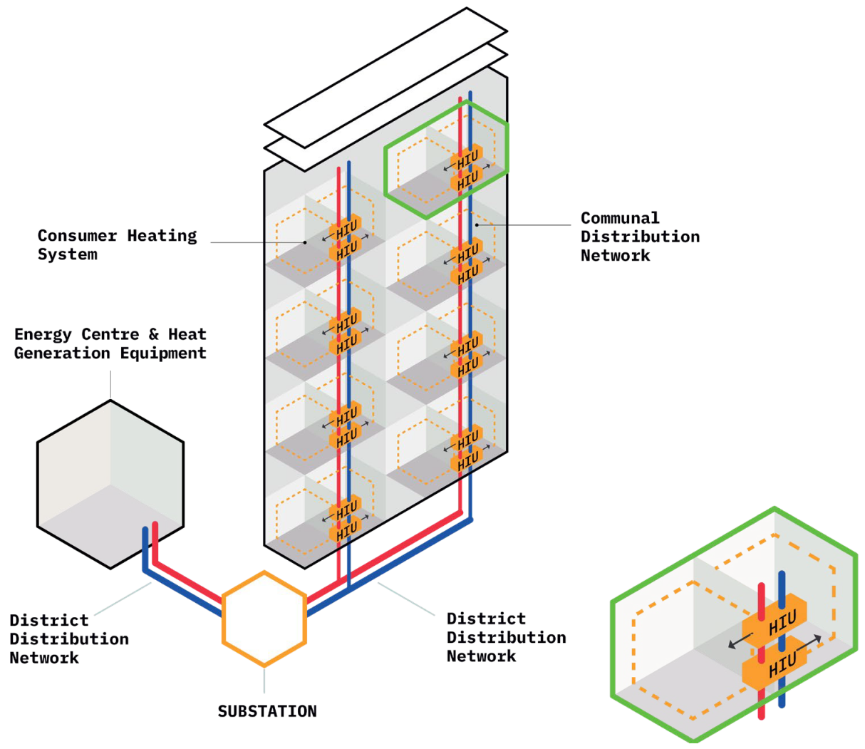
It serves a whole building, a group of buildings or another large consumer.
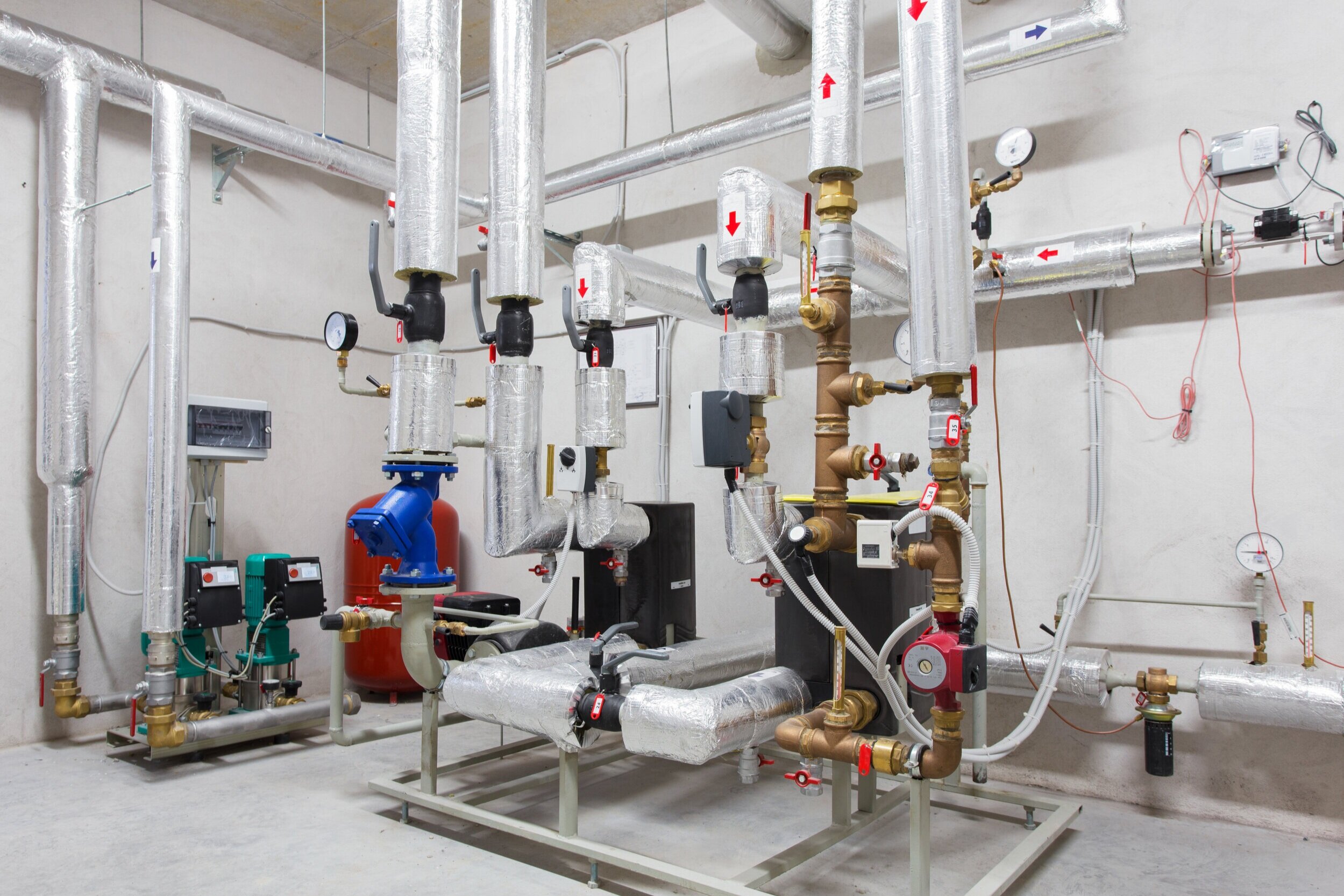
1. Transfer heat
Transfers thermal energy from the district network to the building systems.
2. Control heat delivery
Modulates primary flow and controls the secondary supply temperature according to demand.
3. Protect the connected systems
May provide pressure control, isolation, filtration and safety functions.
4. Separate the circuits where required
In an indirect substation, a heat exchanger separates network water from building-system water.
5. Measure and communicate performance
Provides heat-meter readings, temperatures, flow data, equipment status and alarms where specified.
| Direct connection (hydraulic continuity) | Indirect connection(hydraulic separation) |
|---|---|
| Network water enters the connected building circuit. | A heat exchanger separates network and building water. |
| No interface heat exchanger. | Primary and secondary water do not mix. |
| Fewer components and no exchanger approach temperature (can still require control valves, metering, balancing). | Allows different pressure and water-quality regimes. |
| Building circuit is exposed to network pressure and water-quality conditions. | Usually requires a secondary pump and additional controls. |
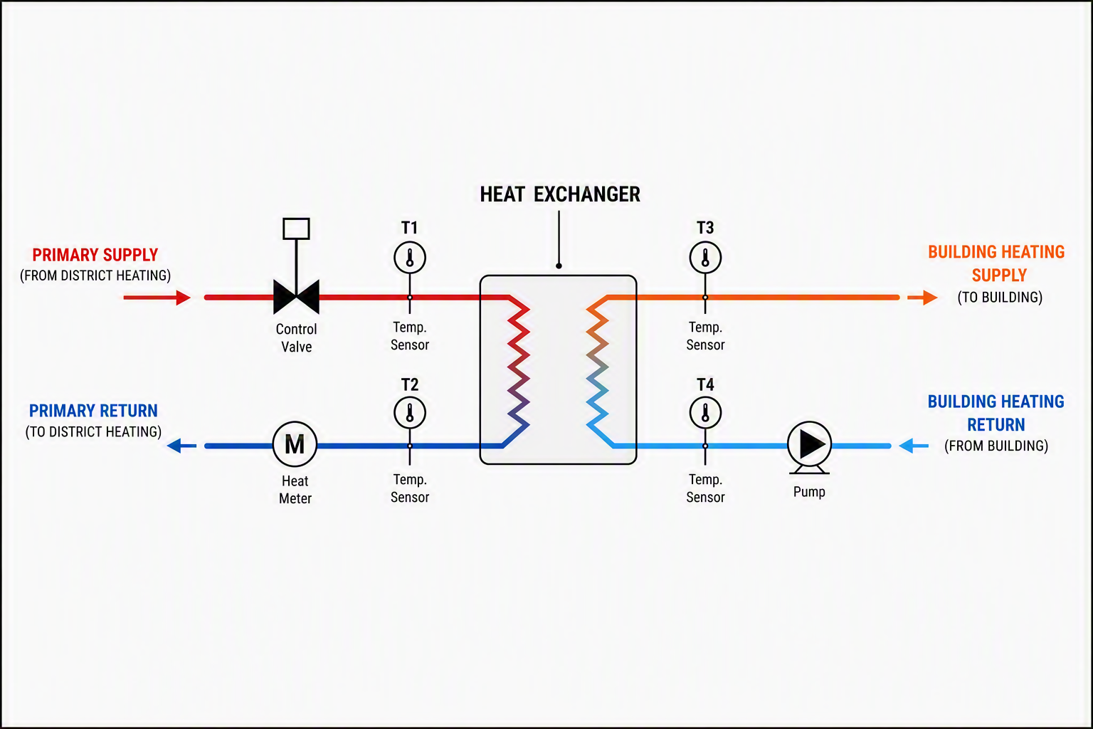
| Component | Function | Basic check |
|---|---|---|
| Plate heat exchanger | Transfers heat without mixing fluids | Correct connections, labels and access |
| Control valve and actuator | Modulates primary flow | Direction, actuator and wiring |
| Differential-pressure controller | Maintains a selected differential pressure across a defined section | Direction and setpoint |
| Secondary pump | Circulates building-side water | Direction, identification and control mode |
| Strainer/dirt separator | Protects equipment from debris | Accessible and cleanable |
| Heat meter and sensors | Measure transferred energy | Direction, meter ID and sensor positions |
1. Identify
2. Inspect
3. Check basic operation
4. Check the evidence
Escalate when
Carry out only authorised, non-invasive checks. Do not open pressurised equipment, alter safety settings or override controls unless competent and authorised.
Always check the approved schematic before assuming what is inside the box.
Used where space heating is supplied
from the communal/building circuit.
Usually includes:
No dwelling heat exchanger. DHW is supplied by a separate system.
What to check:
valve setting, meter direction, sensor pair, labels, access, commissioning record.
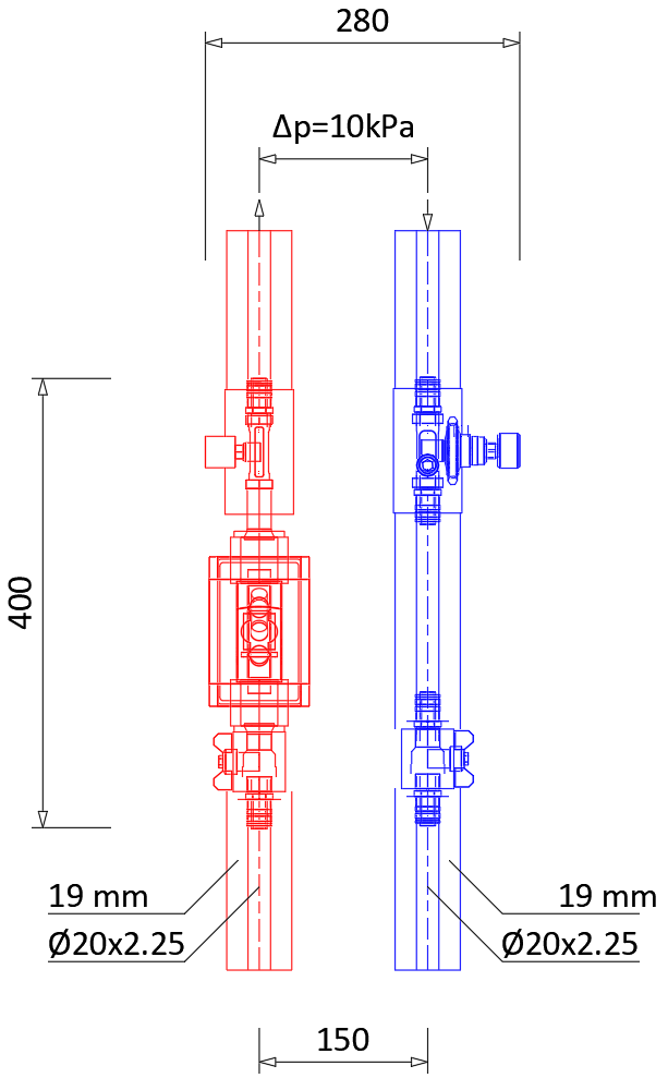
DHW is produced instantaneously through a plate heat exchanger and does not mix with heating water.
Advantages: compact, fewer heating-side losses.
Design and acceptance considerations:
Option B: direct space-heating HIU with local DHW preparation
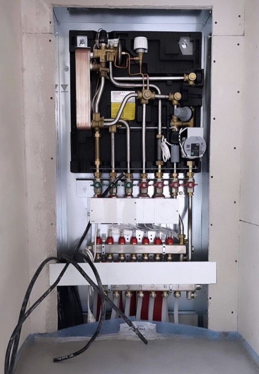
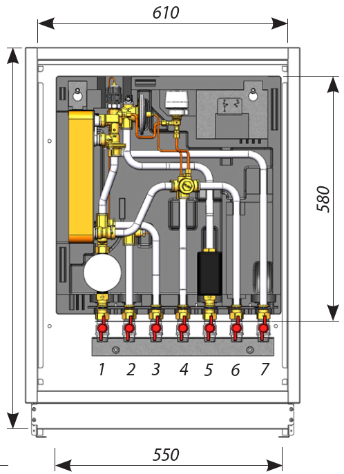
A space-heating PHE separates the dwelling heating circuit from the communal circuit. In a twin-plate HIU, a second PHE produces instantaneous DHW.
Used where separation, pressure control, or safety requirements justify extra equipment.
Trade-off: better hydraulic separation, but more components, pressure drop, commissioning needs.
First identify the arrangement
Then carry out basic checks
A meter records the heat crossing a defined measurement boundary.
It supports:
A heat meter combines flow, temperature difference and time.
ΔT = Tsupply − Treturn
Typical interface-level data
Energy register
kWh
Power
kW
Flow rate
L/h or m³/h
Flow temp
°C
Return temp
°C
Volume
m³
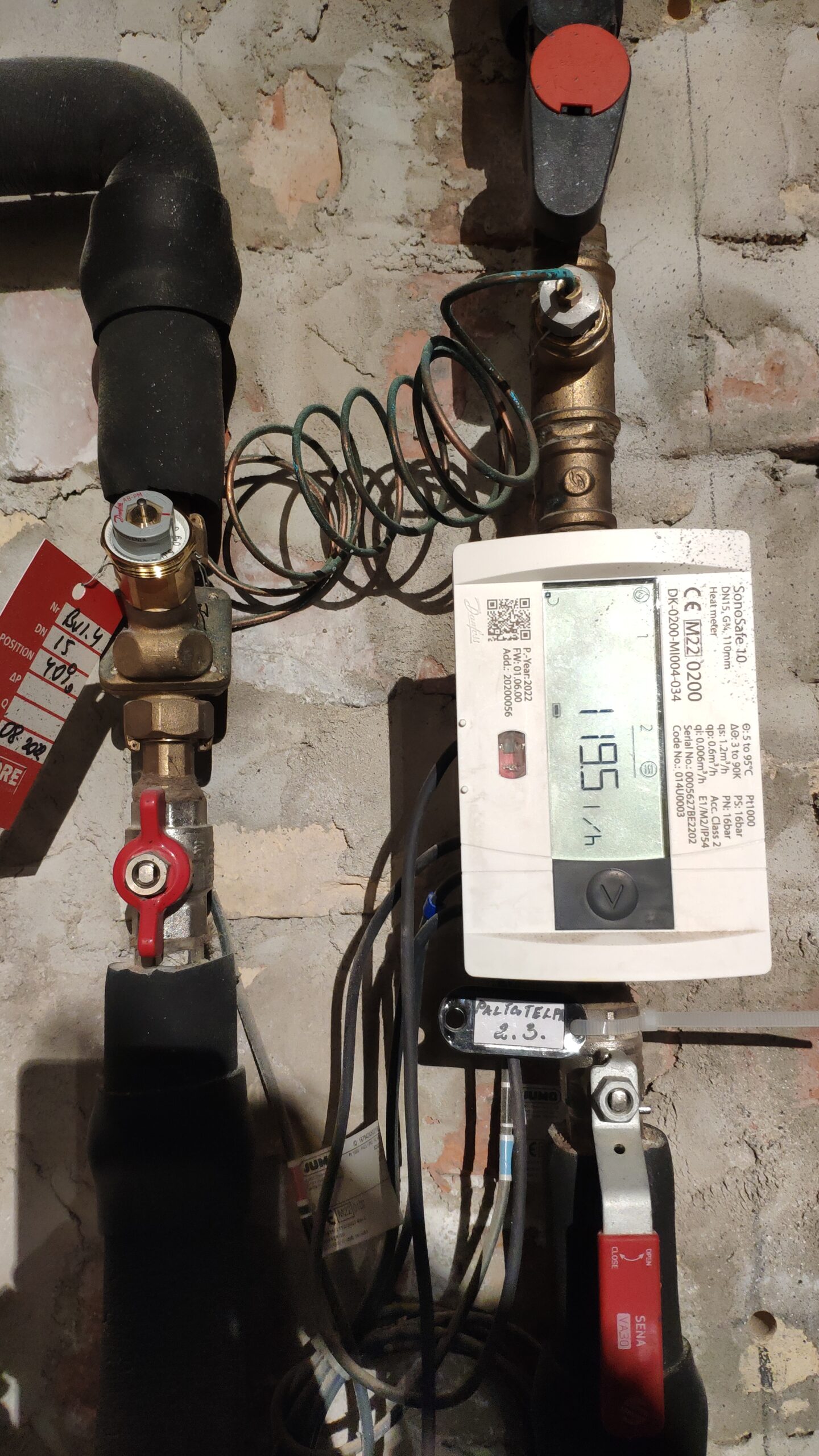
For water, a useful approximate relationship is:
PkW ≈ 1.163 ⋅ Vm3/h ⋅ ΔT°C
QkWh = PkW ⋅ h
Example:
Flow: 0.3 m3/hSupply temperature: 60 ℃
Return temperature: 40 ℃
Operating time: 2 hours
Heating power: PkW = 1.163 ⋅ 0.3 ⋅ (60 − 40) ≈ 7 kW
Heating energy amount: QkWh = 7 ⋅ 2 ≈ 14 kWh
Key distinction!
Power, kW: rate of heat transfer at one moment
Energy, kWh: heat transferred over time
Flow measurement
Temperature measurement
Data and communication
Design errors
Do not check only whether the display is switched on. Check the complete measuring system.
Meter location defines the measurement boundary.
Routine acceptance verifies installation and plausibility;
it does not recalibrate the certified meter.
| Identify | Inspect | Read |
|---|---|---|
| Correct meter and ID | Flow arrow correct | Display active |
| Correct boundary | Sensors in correct pipes | Values and units available |
| Matches drawing/record | Accessible and leak-free | Communication working |
| Legal-metrology evidence available if the meter is used for billing | Seals/identification intact |
During active heating demand
Possible warning signs
One reading identifies a possible symptom;
trends and commissioning evidence are needed to confirm the cause.
Ask to see:
Escalate when:
A dwelling meter shows:
Supply temperature: 62°C
Return temperature: 58°C
Flow: 420 L/h
What is the ΔT?
Calculate heating power in kW.
What might the small ΔT indicate?
What additional information would you request?
Answers:
A system should not be accepted only because it appears to work.
The drawing, the installed equipment and the measured behaviour must tell the same story.
The physical and functional boundary at which thermal energy is transferred between a district heating or cooling network and a building system. It includes the hydraulic connection, heat exchangers, control valves, metering, safety devices, sensors and communication functions needed to deliver energy while protecting both systems.
A packaged unit that connects a dwelling, commercial unit or other individual consumer connection to a communal or district heat network. An HIU may provide space heating, instantaneous domestic hot water (DHW), or both, and commonly includes one or more heat exchangers, control valves, sensors and a heat meter or provision for one. HIUs are not necessarily limited to dwellings and do not always eliminate DHW storage.
An installation serving a whole building, group of buildings or larger consumer that transfers and controls thermal energy between the district network and the building-side systems. It may contain heat exchangers, pumps, control valves, pressure-control equipment, water-treatment provisions, meters, safety devices, instrumentation and supervisory controls.
A hydraulic arrangement in which district-network water circulates directly through all or part of the building heating system without an intervening heat exchanger. It avoids exchanger temperature loss and may simplify equipment, but subjects the building system to network pressure, pressure variations and water-quality requirements; its suitability must therefore be agreed with the network operator.
A hydraulic arrangement in which a heat exchanger separates the district-network circuit from the building circuit. The separation allows the two circuits to operate with different pressures and water-quality regimes and limits cross-contamination. Indirect connection is common but is not universally required.
The primary circuit is the district-network side of an indirect interface. The secondary circuit is the building side, which may include separate space-heating, DHW and cooling circuits. In a direct connection, the primary/secondary distinction may be different or may not apply hydraulically.
A compact heat exchanger formed from a stack of thin, usually corrugated plates that transfers heat between fluids without mixing them. PHEs are widely used in HIUs and substations because they provide high heat-transfer coefficients and a small footprint. Correct sizing must consider design duty, temperatures, allowable pressure drop, fouling and approach temperature.
A valve and its mechanical, thermal or electrical actuator used to modulate or isolate fluid flow in response to a control signal. Selection should consider flow coefficient, pressure rating, close-off pressure, valve authority, leakage class, response time and fail-safe position.
A self-acting or actuated device that maintains a selected differential pressure across a defined part of the primary circuit. It stabilizes valve authority and flow control when network pressure varies. The controlled section and setpoint must be stated; a DPC does not by itself guarantee correct ΔT.
A device that circulates fluid through a building-side or local primary circuit. Pumps should be selected and commissioned for the required duty and control mode; excessive pump head or uncontrolled constant-speed operation can increase electricity use, noise and hydraulic imbalance.
A device installed to capture debris, magnetite or suspended solids before they reach heat exchangers, control valves, pumps or meters. It must be accessible for cleaning and checked during commissioning because a blocked strainer can cause low flow, unstable control and loss of duty.
Equipment that accommodates thermal expansion and maintains the required static pressure in a closed secondary circuit. Acceptance checks include pre-charge or operating pressure, vessel size, relief-path integrity and compatibility with system volume and temperature range.
A pressure-activated safety device that discharges fluid when pressure exceeds its set value. It protects equipment from overpressure and must have the correct set pressure, capacity, orientation and safe discharge arrangement.
The preparation of domestic hot water on demand by transferring heat through a heat exchanger, without storing a significant volume of hot potable water in the HIU. It can reduce stored-water heat loss and the volume in which Legionella may multiply, but it requires adequate primary temperature, flow, exchanger capacity and control response at peak draw-off.
A control strategy that temporarily gives domestic hot-water production priority over space heating when DHW demand occurs. It limits the required coincident peak capacity but must maintain acceptable comfort, stable DHW temperature and suitable primary return temperature.
A function that maintains part of an HIU, riser or primary branch at an elevated temperature to reduce DHW waiting time. It can improve service but increases heat loss and may raise return temperatures, so its temperature, schedule and control logic should be minimized and verified.
A control strategy that varies the secondary space-heating supply temperature according to outdoor temperature and, where applicable, other inputs. The objective is to meet comfort demand with the lowest practical flow temperature, supporting lower return temperatures and reduced heat loss.
The defined relationship between outdoor temperature and the target secondary heating supply temperature. During commissioning, the curve, limits and setbacks should be checked against the building design and terminal-unit requirements.
An instrument that determines transferred thermal energy from measured fluid flow and the temperature difference between paired temperature sensors. For billing, the meter and its installation must meet applicable legal-metrology requirements. In the EU, heat meters are covered by the Directive 2014/32/EU, known as MID (Measuring Instruments Directive); the EN 1434 series provides relevant technical requirements.
The meter component that measures the volume or mass of heat-transfer fluid passing through the circuit. Correct direction, orientation, straight-length requirements where applicable, fluid condition and absence of air are important for accurate measurement.
Two temperature sensors selected and characterized as a pair to measure supply and return temperatures for a thermal energy meter. They must be installed in the correct locations and fully inserted or mounted as specified; swapping, uneven immersion or poor thermal contact can create significant energy-measurement error.
A check that the correct approved meter is installed in the specified position and direction, with matched sensors, intact seals, correct configuration, communications and readable identifiers. Routine site acceptance normally verifies installation and plausibility rather than recalibrating a legally certified meter.
Accuracy describes closeness to the true value under stated conditions; calibration establishes the relationship between indicated and reference values. Overall uncertainty includes sensor error, installation effects, flow profile, temperature-sensor pairing, time alignment and data processing. Small delta-T measurements can have high relative uncertainty, so KPI thresholds must be compatible with the metering system’s capability.
The frequency at which values are measured, recorded or transmitted, together with the alignment of device clocks. Averages that are too coarse can hide cycling, short outages, flow spikes and control instability. Unsynchronised flow, temperature and electrical data can create false energy balances, especially during rapid changes.
Processes used to identify missing, duplicated, frozen, out-of-range or physically inconsistent data. Validation may use sensor cross-checks, energy balances, equipment-state logic and comparison with redundant measurements. Data correction or gap filling should be traceable and should not silently convert estimates into measured performance.
Time-stamped recording of abnormal conditions, operator actions, equipment starts, trips, setpoint changes and communication failures. Useful alarms should have defined thresholds, delays, priorities, acknowledgement rules and response procedures. Excessive nuisance alarms can obscure critical faults and reduce operational effectiveness.
Preparatory work completed before functional commissioning, including inspection, cleaning and flushing, pressure testing, water-quality confirmation, electrical checks, completion of records and confirmation that the system is safe and ready to operate.
The planned process of setting to work, adjusting, testing and documenting an HIU or substation so that it performs in accordance with the approved design and operating requirements. Commissioning includes static checks, functional testing, balancing, control tuning, performance tests and recording of final settings.
The documented verification used by the client, owner or network operator to decide whether the installed interface complies with the contract, approved design, applicable regulations and agreed performance criteria. Acceptance may include witnessed commissioning results, inspections, document review and closure of defects.
A visual and documentary check confirming correct equipment, orientation, accessibility, supports, insulation, labels, valves, drains, vents, sensor locations, electrical connections and conformity with approved drawings and manufacturer instructions.
A controlled test confirming that specified circuits and joints can withstand the prescribed test pressure and are leak-tight. The medium, pressure, duration, exclusions, temperature allowance and acceptance criteria must follow the applicable code, specification and equipment limits; pressure should not be applied indiscriminately above normal operating pressure.
The controlled circulation and discharge of fluid to remove installation debris and contaminants, followed by evidence that cleanliness meets the project specification. The method should protect sensitive components and may require temporary bypasses, high-velocity flushing, strainer inspection or sampling.
Testing and documentation showing that network and secondary-circuit water meets the relevant operator, manufacturer and water-treatment requirements. Parameters depend on materials and system type and may include pH, conductivity, hardness, dissolved oxygen, inhibitor concentration, microbiological condition and suspended solids; a universal checklist is not appropriate for every system.
A structured test demonstrating that equipment and controls perform their intended functions through normal, part-load, transition, fault and recovery conditions. For an HIU or substation this can include valve modulation, DHW priority, temperature control, pump sequencing, weather compensation, flow limiting, alarms, communications and fail-safe behavior.
A performance test confirming that the interface can deliver the specified heating, DHW or cooling duty at the stated primary and secondary temperatures, flow conditions and differential pressure. Results should be compared with agreed tolerances and corrected for test conditions where necessary.
A test or monitored assessment confirming that the primary return temperature or ΔT meets the specified target in each relevant operating mode and over defined load conditions. Testing only at a single design point is usually insufficient; DHW, space-heating, standby and part-load behavior should be considered.
A test of the ability of the control system to reach and maintain setpoints without unacceptable oscillation, overshoot or delay when demand or network conditions change. It is particularly important for instantaneous DHW and modulating primary valves.
Verification that the complete potable-water design, temperatures, volumes, flushing arrangements and operating strategy comply with the applicable local hygiene and scald-protection requirements. Instantaneous production reduces stored hot-water volume but does not by itself remove all microbiological risk, and no single universal temperature threshold should be assumed.
Verification of protective devices, earthing, isolation, wiring, enclosure, emergency functions, controller configuration and electrical test records in accordance with applicable regulations and manufacturer requirements.
An inspection and, where required, measurement confirming that pumps, valves, pipework and the packaged unit do not produce unacceptable airborne or structure-borne noise under representative operating conditions. The test should use the project’s stated acoustic criteria and locations.
A check that each physical and digital input/output is correctly mapped between field devices, the local controller, BMS and remote monitoring platform. Commands, values, units, alarms, time stamps and communication-loss responses are verified.
A commissioning or performance test observed by an authorized representative of the client, owner, network operator or independent assessor. Witnessing confirms that the agreed procedure was followed but does not transfer responsibility for the contractor’s work.
A controlled record of incomplete, damaged or non-compliant items identified during inspection and testing, including responsibility, required action, priority and closure evidence. Safety-critical or performance-critical defects should be closed before acceptance.
The verified record set provided at handover, normally including as-built drawings and schematics, equipment schedules, certificates, pressure and flushing records, water-quality results, commissioning sheets, meter details, final setpoints, control descriptions, software backups, alarm lists, operating manuals, maintenance requirements, warranties and training records.
Follow-up testing and optimization after handover when representative seasonal loads and occupancy are available. It confirms heating-curve settings, return-temperature performance, control schedules and user outcomes that could not be fully demonstrated during initial acceptance.
The practice-question document includes answers and explanations for self-study.
When you are ready, take the Unit 2 quiz.