

Module 4 · Unit 4
Read the unit content below, then use the case studies and key terms to review what you have learned.
By the end of this session, learners should be able to:
Flexibility is the ability of a heat-network system to change:
The system should adapt while maintaining comfort, domestic-hot-water service, safety and stable network operation.
Flexibility changes the timing or source of heat, not the required service to the user. Flexibility should be described by service, magnitude, duration, response time, location and recovery effect.
Thermal flexibility
Changing the timing of heat production or consumption using:
Operational flexibility
Changing which equipment operates, when it starts and what output it provides.
Sector coupling
Coordinating heating with the electricity system through:
Sector coupling is beneficial only when electricity price/carbon signal, conversion efficiency and network constraints support it.
Heat-production flexibility
Storage flexibility
Consumer-side flexibility
Signals that activate flexibility
Flexibility can respond by:
Flexibility connects energy available at one time with heat demand occurring at another.
Thermal energy storage separates the timing of:
Storage can help:
Storage is one flexibility option. Its value depends on system size, heat sources, load profile, losses and operating strategy.
Hot-water tank storage
Network thermal inertia
Long-duration storage may shift heat across days or weeks;
seasonal storage shifts heat across seasons or many months
Examples:
Building thermal mass can act as a limited virtual thermal store when pre-heating, pre-cooling or temporary setpoint changes are controlled within comfort limits.
A control strategy may:
Limits
Temperatures
top, middle and bottom tank temperatures;
charge and discharge temperatures;
network supply and return temperatures.
Flow and power
charge flow;
discharge flow;
calculated thermal power;
pump status and speed.
Storage condition
estimated state of charge;
available capacity;
stratification quality;
standing heat loss.
Control status
charge command;
discharge command;
operating mode;
valve position;
active limits and alarms.
Warning patterns
charging command but no temperature rise;
simultaneous charging and discharging;
rapid loss of stratification;
high flow with little transferred heat;
state of charge inconsistent with measured temperatures.
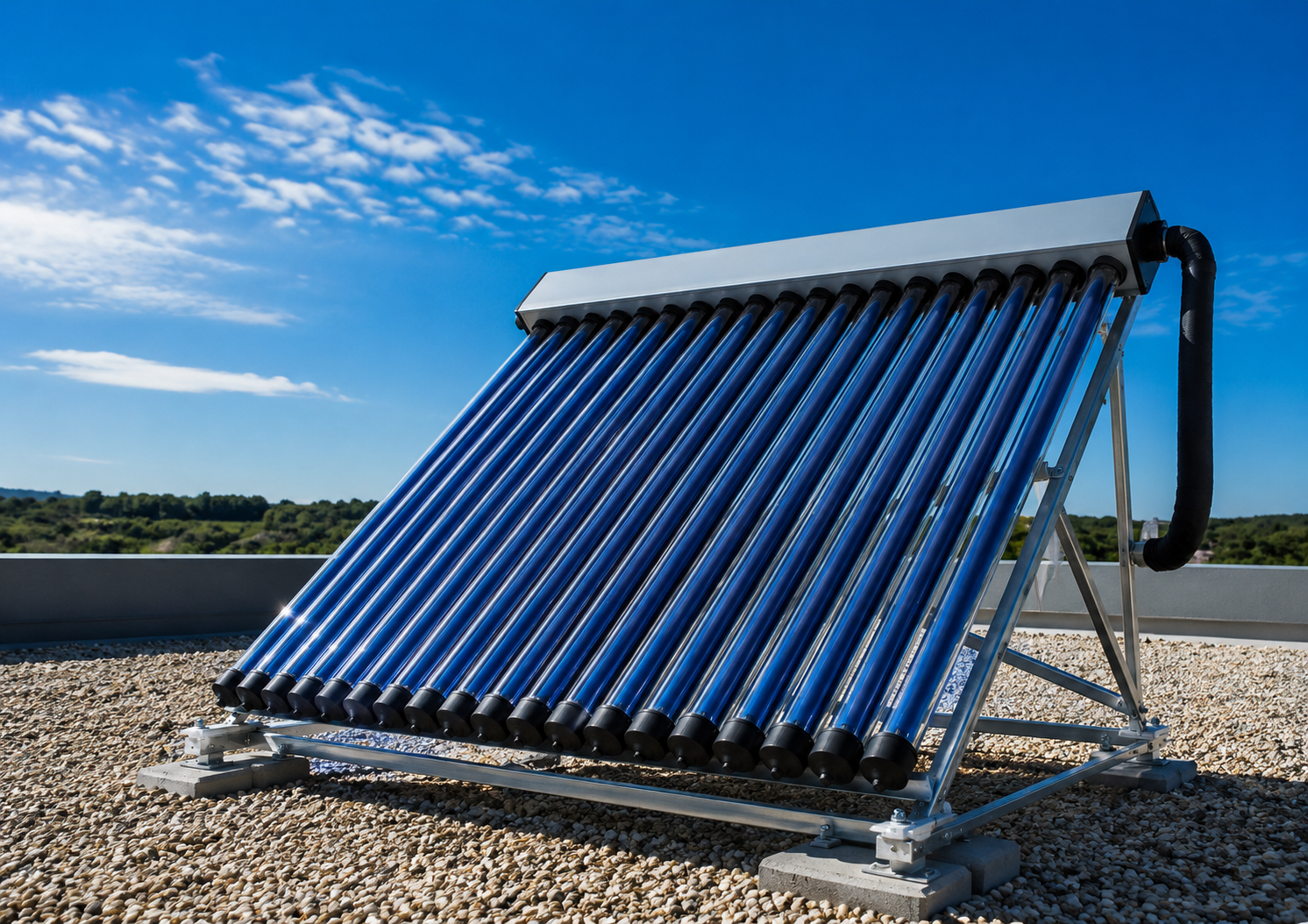
A solar collector converts solar radiation into heat in a circulating fluid.
A district-heating installation may include:
At the same solar irradiance, useful collector output decreases as the collector fluid temperature rises above ambient; therefore lower network temperatures increase useful solar yield.
FPC – flat-plate collector; ETC – evacuated tube collector
Tm,f – mean fluid temperature in the collector, °C; Ta – ambient air temperature, °C.
The dependence of the thermal output of solar collectors on the temperature difference at the intensity of solar irradiation of 1000 W/m2
| ST collector | η0 | a1 | a2 |
|---|---|---|---|
| FPC Nr.1 | 0.831 | 3.08 | 0.0100 |
| FPC Nr.2 | 0.773 | 2.27 | 0.0181 |
| FPC Nr.3 | 0.613 | 5.45 | 0.0109 |
| ETC Nr.1 | 0.608 | 1.14 | 0.0012 |
| ETC Nr.2 | 0.568 | 1.04 | 0.0024 |
| ETC Nr.3 | 0.368 | 0.61 | 0.0046 |
Solar thermal is easier to use when the network requires a lower temperature.
Benefits include:
System performance also depends on:
Daily mismatch
Solar production is concentrated around daylight hours, while building demand may peak in the morning or evening.
Seasonal mismatch
Solar output is highest in summer, while space-heating demand is highest in winter.
Operational consequence
Without a suitable heat sink, output may need to be:
Flexibility options
Expected daily pattern
solar irradiance rises after sunrise;
collector temperature increases;
circulation begins when useful temperature difference is available;
thermal power rises around midday;
output falls as irradiance decreases;
circulation stops when useful heat transfer is no longer possible.
Monitor
solar irradiance;
collector inlet and outlet temperatures;
collector flow;
thermal power and energy;
storage temperatures and state of charge;
pump status;
heat-exchanger temperatures;
stagnation or overtemperature alarms.
Possible faults
irradiance present but no collector flow;
pump running with no useful temperature rise;
high collector temperature but no heat transfer;
frequent pump cycling;
storage fully charged while collectors continue ting.
Deep geothermal
may provide heat at a temperature suitable for:
Shallow geothermal
usually provides lower-temperature heat through:
A heat pump commonly raises the temperature for useful heating.
Strengths
Constraints
Source side
extraction temperature;
reinjection or return temperature;
source flow rate;
well or loop pressure;
pump status and electrical use;
annual heat extraction/rejection balance and long-term temperature drift.
Heat-transfer side
heat-exchanger inlet and outlet temperatures;
heat transferred;
approach temperature;
fouling or pressure drop.
Heat pump, where used
evaporator and condenser temperatures;
thermal output;
electrical input;
COP;
start/stop frequency;
alarms and operating limits.
Long-term warning signs
falling source temperature;
rising pumping power;
reduced flow;
scaling or fouling;
excessive cycling;
imbalance between annual heat extraction and regeneration.
1. Measurements
heat demand;
temperatures;
flow and pressure;
storage state of charge;
source availability;
weather or electricity signal.
2. Control rules
Examples:
charge storage when renewable heat is available;
discharge during peak demand;
stop charging at maximum temperature;
preserve minimum reserve capacity;
maintain consumer comfort and DHW requirements;
set minimum run times, deadbands and controller priority.
3. Commands
start/stop heat source;
modulate pump speed;
open or close valve;
charge or discharge storage;
adjust building demand.
4. Feedback and alarms
verify that the command produced the expected response;
alarm if temperatures, flow or equipment state are inconsistent.
| System area | Minimum useful points |
|---|---|
| Network | supply/return temperature, flow, pressure, thermal power |
| Heat sources | available capacity, output, operating state, alarms |
| Heat pump | heat output, electrical input, COP, starts and run time |
| Thermal storage | temperatures, flow, charge/discharge power, SoC |
| Solar thermal | irradiance, collector temperatures, flow, output |
| Geothermal | source temperature, flow, pressure, pump power |
| Buildings | heat demand, indoor temperature where permitted, operating mode |
| Controls | setpoints, valve commands, pump commands, schedules |
| External signals | outdoor temperature, forecast, electricity price or carbon signal |
Possible symptoms
frequent heat-pump starts and stops;
storage alternates rapidly between charge and discharge;
renewable heat is curtailed while backup heat operates;
storage reaches maximum or minimum state of charge too early;
source output repeatedly overshoots demand;
return temperature and flow oscillate.
Possible causes
incorrect start/stop thresholds;
insufficient storage capacity or charge power;
poor forecasting;
minimum equipment output higher than demand;
inaccurate state-of-charge estimate;
conflicting controllers.
First checks
compare demand, source output and storage power on the same time axis;
review minimum run time and deadband;
confirm sensor accuracy;
check which controller has priority.
A smart-control platform may combine:
Important conditions
advanced optimisation requires:
Predictive control cannot compensate for faulty sensors, poor commissioning or unclear operating limits.
Flexibility is valuable when it shifts heat intelligently without compromising service, efficiency or equipment operation.
A reference collection of real-world projects for student research.
It is organised into three themes:
1) thermal energy storage,
2) renewable (solar/heat pump) integration, and
Each entry gives the project name, core parameters, and a link to find more detail.
Several projects appear in more than one section (e.g., Vojens, Braedstrup, Varanto) because real DH decarbonisation projects typically combine storage, renewables, and waste heat rather than using a single technology in isolation - worth highlighting when comparing case studies.
World's largest pit thermal energy storage: a 200,000 m3 earth basin charged by a 70,000 m2 solar collector field (one of Europe's largest). Surplus summer solar heat is stored and discharged into the DH network in winter, operated by Vojens Fjernvarme.
https://www.solmax.com/global/en/case-studies/worlds-largest-pit-thermal-storage-in-vojens
An 85,000 m3 earth-basin PTES that stores solar heat collected in summer for release into the local DH network in winter, part of Toftlund's solar-plus-storage DH concept. https://www.solmax.com/global/en/case-studies/pit-thermal-storage-in-toftlund-denmark
Long-running demonstration of-100% renewable DH combining a -75,000 m3 seasonal pit storage with a large solar collector field, showing that solar can cover 50%+ of annual heat demand without biomass. 6' https://www.solar-district-heating.eu/ (search "Marstal") and https://bankwatch.org/wp-content/uploads/2022/05/2022-05_Case-Study-Marstal_eng.pdf
A 62,000 m3 PTES paired with a -35,000 m2 solar collector field and seasonal storage, one of the reference plants used in Danish/EU PTES performance studies (PlanEnergi/Solites/DTU).
https://www.iea-dhc.org/home (Annex XII Task C report, Task C project 03)
The first large-scale short-term (non-solar) PTES: 70,000 m3, 30 MW charge/discharge capacity, 3,300 MWh storage capacity, cycled 25-30 times per year to buffer CHP and waste-incineration heat for greater Copenhagen's DH grid. Includes an open research monitoring dataset.
https://github.com/PitStorages/HojeTaastrupData
and
https://www.sciencedirect.com/science/article/pii/S2352152X25022170
Under construction seasonal storage in three excavated bedrock caverns (20 m x 300 m x 40 m each,1.1 million m3 total, up to100-140 m below ground). Water is pressurised to reach up to140 °C. Capacity 90 GWh - enough to heat a mid-sized Finnish city for a year; will store surplus waste-to-energy and electric-boiler heat. Expected online -2028-2030.
Varanto – The Cavern Thermal Energy Storage
Combines an 18,600 m2 solar collector field (integrated into a gas-fired CHP plant) with a borehole seasonal storage (19,000 m3 of underground strata, -500 MWh at 65 °C) plus water tanks and a1.5 MW heat pump to boost stored heat to 80 °C for the grid.
Brædstrup district heating
and
Solar district heating systems in Denmark
A modelling case study (DTU) of a hypothetical PTES combined with an air-to-water heat pump and electric boiler in Viborg's DH system, showing -10% reduction in levelised cost of heat and a 5.1-year payback versus a system without storage.
https://orbit.dtu.dk/en/home/index/ (search "Investigations of pit thermal energy storages in district heating systems")
Both combine very large solar collector fields (70,000 m2 and -36,000 m2 respectively) directly with DH networks; useful paired examples of solar-DH at different city scales.
Home
First plant worldwide to integrate solar thermal into a natural-gas CHP DH system (2007), later expanded with a groundwater heat pump and borehole storage; illustrates sector coupling between solar heat, gas CHP, and electricity markets.
Solar district heating systems in Denmark
Denmark passed 1,000,000 m2 of installed solar collectors across 85 municipal DH networks - a good entry point for browsing dozens of individual solar-DH plants (Gram, Silkeborg, Toftlund, etc.) by size and configuration.
1 Million Square Meters Solar Thermal Collectors in Danish District Heating Plants
World-renowned large-scale natural-refrigerant (ammonia) seawater heat pump: -14-15 MW, COP: 3.15, extracting heat from fjord water at 8-9 °C and delivering 90 °C DH water to -60,000 residents; powered by Norwegian hydropower for near-zero operating emissions. Operating since 2011.
The world’s largest 90°degree C natural heat pump for district heating
and
Drammen Neatpump
One of the largest seawater heat pumps in Europe and the largest CO2 (R744) heat pump worldwide at commissioning:-60-70 MW heat, transcritical CO2 cycle, drawing seawater from the North Sea to supply DH at 60-90 °C forward temperature.
https://heatpumpingtechnologies.org/project57/ (Task 2 Denmark case study, Esbjerg)
90 MW combined heat-and-cooling heat pump plant using district cooling return water (summer) and ambient/sea water (winter) as heat sources - an example of integrated heating/cooling heat pump operation in a dense city network.
https://www.helen.fi/en/news/2023/Waste-heat-plays-a-significant-role-in-a-sustainable-energy-system
Stockholm's DH system has used heat pumps since 1977 (originally recovering IBM server heat) and now operates roughly 660 MW of heat pump capacity using treated sewage water, seawater, district cooling return, data centres, and grocery-store cooling as heat sources - a good "portfolio" example of multi-source urban heat pump integration.
https://www.stockholmexergi.se/
Two mechanical heat pumps serially pre-heat DH return flow using internal process heat (flue-gas condensate, turbines, compressors) from a waste-to-energy plant - illustrating heat pumps embedded directly in generation processes rather than external sources.
https://www.stockholmexergi.se/arsredovisning-2025/en/production/distribution-system/
(Search "Brista 2 Stockholm Exergi heat pump")
8000 m³ thermal energy storage tank in Salaspils district heating system
In 2019, SIA “Salaspils Siltums” implemented a project that included the construction of an 8,000 m³ thermal energy storage tank, a solar collector field, and a 3 MW wood chip boiler house. The storage tank is part of a larger RES integration system that allows the storage of heat generated by solar collectors during off-peak hours and its use later when consumers need heat.
The main function of the storage tank is to store heat and balance the parameters of the district heating system. In the case of Salaspils, it is an approximately 28 m high structure in which the heat generated by solar collectors can be stored for several days, thus increasing the efficiency of solar collectors.
Sources: SIA “Salaspils Siltums” material “Accumulation tank in district heating” and description of the EU funds project on the transition of the heat source to RES.
https://salaspilssiltums.lv/akumulacijas-tvertne-centralizetaja-siltumapgade/
Solar collector field in Salaspils district heating system
The Salaspils solar heat project is one of the best-known examples of RES integration in district heating in the Baltics. The project installed 1,720 solar collectors on an area of 6.5 ha, built an 8,000 m³ storage tank and a 3 MW wood chip boiler house. The project’s goal was to increase the share of renewable energy resources in heat supply and ensure a significant share of summer heat consumption with solar energy.
According to the Solar Heat Europe case study, the total collector area of the Salaspils solar collector field is 21,672 m², the installed solar heat capacity is 15 MWth, and the expected annual energy supply is around 12 GWh. After the project was implemented, the share of RES in heat production in Salaspils significantly increased, including around 20% of the annual heat energy provided by solar energy.
Sources: Solar Heat Europe case study “A 90% renewable district heating network” and SIA “Salaspils Siltums” project descriptions on the use of solar energy in Salaspils.
A 90% renewable district heating network
Use of waste heat from Tet DC7 data center in Salaspils heating supply
A solution for using waste heat from a data center in district heating is being developed in Salaspils. SIA “Salaspils Siltums” informs that the Tet data center project plans to transfer the heat energy generated during the data center’s operation to the company “Salaspils Siltums” to be used in the district heating of local residents - for water heating in the summer, and for heating in the winter.
This example is especially valuable for students because it demonstrates the industrial symbiosis approach: a data center requires cooling, while a district heating system requires a heat source. Salaspils municipality information about DC7 indicates that the data center will use innovative liquid cooling solutions, but the heat produced will be used in Salaspils’ district heating. Publicly available materials also mention that the implementation of such a solution will require heat pumps to raise the temperature of the incoming waste heat to a level usable for district heating.
Sources: News from SIA “Salaspils Siltums” about the Tet data center project and information from Salaspils municipality about the DC7 data center.
https://salaspilssiltums.lv/salaspili-planots-izbuvet-datu-centru-kas-nodos-siltumu-sia-salaspils-siltums/
https://salaspils.lv/lv/node/3751
The ability of an energy system to modify generation, conversion, storage, network operation or demand over time in response to expected or unexpected changes while respecting technical limits, safety, comfort and service-quality requirements. Flexibility must be described by the service provided and by its magnitude, duration, response time, location and recovery effects; it is not a single universal capacity.
The capability of a district heating or cooling system to vary heat or cold production, source selection, storage charging and discharging, network temperatures, flows and customer demand. Useful flexibility may support thermal-network operation, renewable integration, electricity-system operation, cost reduction, emissions reduction or resilience, but these objectives can conflict and therefore require explicit prioritisation.
A flexibility resource is the physical or operational asset that can change its behaviour, such as a heat pump, electric boiler, CHP unit, thermal store, building or controllable process. A flexibility service is the system need that the change fulfils, such as peak reduction, energy shifting, reserve provision, congestion relief or renewable-energy utilisation. The resource and the service should not be treated as interchangeable terms.
The characteristics used to quantify a flexibility option: adjustable thermal or electrical power, usable energy, activation duration, response time, ramp rate, run time, recovery time, availability, location, efficiency and number of permissible activations. Technology can be highly flexible in one area and unsuitable in another.
The ability to alter the output, operating point or source mix of heat- and cold-production assets. Examples include modulating heat pumps and boilers, changing CHP operation, switching between sources, varying network temperature within limits and charging or discharging storage. Constraints may include minimum load, start-up time, ramp rate, source availability, emissions and equipment wear.
A temporary, controlled change in heat or cooling demand relative to an expected baseline in response to a signal such as a tariff, dispatch instruction, network constraint or renewable-availability forecast. Actions include pre-heating, pre-cooling, setpoint adjustment, DHW scheduling and temporary load reduction. Comfort, hygiene, process requirements and rebound must be respected.
The estimated consumption or operating profile that would have occurred without a flexibility activation. It is needed to quantify the delivered response and may be based on historical data, weather-normalised models, control schedules or a reference simulation. Baseline uncertainty can be a major source of error in demand-response evaluation and settlement.
Coordinated planning and operation across energy carriers and end-use sectors, especially electricity and heating/cooling. District energy can couple sectors through heat pumps, electric boilers, CHP, thermal storage and shared control. Coupling is beneficial only when conversion losses, infrastructure constraints, prices, emissions and interactions between networks are considered.
Conversion of electricity into useful heat using equipment such as resistance or electrode boilers and heat pumps. The heat can meet immediate demand, raise a network temperature or charge storage. Power-to-heat does not inherently use surplus renewable electricity and does not automatically provide a grid service; this depends on dispatch, electricity mix, controls and market qualification.
Useful heating or cooling supplied from renewable energy sources under the applicable accounting rules. Examples can include solar thermal, geothermal energy, sustainably sourced bioenergy and ambient energy captured by heat pumps. Renewable status is an accounting and regulatory attribute and should not be assumed solely from low operating emissions.
The coordinated use of flexibility to accommodate renewable production that changes with weather or time, such as solar thermal output and wind- or solar-generated electricity used by power-to-heat equipment. Ambient heat is a renewable source for heat pumps but is not normally classified as variable renewable electricity. Variability, predictability and dispatchability should be stated separately.
Renewable heat whose output can be scheduled or controlled within technical and resource limits, for example sustainable bioenergy, reservoir-supported geothermal heat or stored solar heat. Dispatchability is not absolute: fuel availability, storage level, environmental permits, minimum load and equipment constraints still apply.
Low-temperature energy available from air, surface water, groundwater, soil or other environmental sources and upgraded by a heat pump where necessary. Its usable output depends on source temperature, seasonal variation, extraction limits, environmental constraints and the required temperature lift.
A district heating system in which solar thermal collectors supply useful heat to the network, directly through an interface or via short-term or seasonal storage. Solar contribution is weather- and season-dependent, and integration design must address collector temperature, return temperature, stagnation, land area, storage and backup supply.
The use of heat extracted from geological formations or groundwater to supply a district network, directly where the source temperature is sufficient or through heat pumps where upgrading is required. Resource temperature, sustainable extraction rate, reinjection, mineral chemistry, drilling risk and local geology determine performance.
Thermal energy generated as a by-product of another process and captured for useful application instead of being rejected. The terms are often used differently in engineering, contracts and legislation; recovered heat is not automatically renewable. Assessment must consider temperature, continuity, location, ownership, alternative uses, additional energy for recovery and the risk that the host process changes or closes.
Heat available at a temperature too low for direct use in the intended application or network condition, but potentially usable through lower network temperatures, cascading, heat exchange or a heat pump. “Low-grade” refers to temperature quality and exergy, not to poor reliability or low economic value.
Source temperature is the temperature level from which useful heat is recovered. Temperature lift is the difference between the heat-pump source and sink temperature levels, defined using stated measurement points. A smaller lift generally improves heat-pump efficiency and capacity, while network return temperature and required supply temperature strongly influence the lift.
A system that charges, retains and later releases thermal energy as heat or cold, thereby decoupling the timing of thermal production from use. Storage may be sensible, latent or thermochemical and may operate over minutes, hours, days or seasons. It enables flexibility but is not automatically essential or economic in every district-energy system.
Storage capacity is the thermal energy associated with a stated temperature, phase or reaction range. Usable capacity is the portion that can actually be charged and discharged while respecting minimum and maximum temperatures, state-of-charge limits, heat-exchanger approach, network requirements and reserve margins. Nameplate and usable capacity are therefore not necessarily equal.
The maximum or operating rate at which thermal energy can be added to or removed from storage. Power is distinct from energy capacity and may be limited by pumps, wells, heat exchangers, temperature differences, stratification, ground conductivity or process constraints. Separate charge and discharge ratings may be required.
An estimate of the currently usable stored energy relative to defined minimum and maximum states. For a well-mixed water tank it may be related to temperature; for stratified, underground, latent or thermochemical stores it may require a model or multiple measurements. The reference temperatures and calculation method should be stated.
The time for which a store can discharge at a stated power before reaching its minimum usable state, commonly approximated as usable energy divided by discharge power. Duration does not alone describe response speed, seasonal retention or the ability to repeat activations.
The useful thermal energy recovered from a complete charge-storage-discharge cycle divided by the energy used to charge the store, with the system boundary clearly stated. Pumping, heat-pump electricity, auxiliary heating and temperature quality may need separate treatment; a heat-only energy ratio can hide exergy or electricity penalties.
The reduction in usable stored energy with time when no useful discharge occurs, caused by heat transfer to the surroundings, groundwater movement, mixing or material processes. The rate depends on geometry, insulation, temperature difference, storage duration and boundary conditions and is especially important for long-duration storage.
The formation of layers at different temperatures, normally with warmer, less-dense water above colder water. The thermocline is the transition zone between layers. Preserving stratification can increase usable temperature quality and reduce mixing losses; poor inlet design, excessive flow and internal circulation can degrade it.
Repeated charging and discharging of a store. Cycling frequency and depth influence losses, operating cost and, for some materials or equipment, degradation. Underground stores may also require several years of thermal development before reaching stable seasonal performance, so first-year results may not represent mature operation.
Thermal storage used mainly to smooth short-term differences between production and demand, reduce cycling, provide hydraulic separation or shift energy over minutes to several days. “Buffer” describes function rather than a universal size or duration; the appropriate volume depends on the required power, energy and control objective.
A water tank designed to maintain temperature layers through suitable geometry, diffusers, flow rates and control. It can provide rapid charging and discharging and is widely used for daily balancing. Performance should be assessed by usable energy, temperature quality, heat loss, pressure arrangement and degradation of the thermocline.
The temporary storage effect provided by the thermal mass of water and pipes in a district network when temperatures are varied within acceptable limits. It can shift heat production over short periods without a separate tank, but available energy is location-dependent and constrained by customer supply temperatures, transport delay, heat loss and hydraulic operation.
Use of the heat capacity of the building fabric and indoor environment to shift heating or cooling demand through controlled pre-heating, pre-cooling or temporary setpoint changes. It is a flexibility resource rather than a separately contained store and is constrained by comfort, occupancy, building dynamics, weather, ventilation and rebound.
Large-energy-capacity storage intended to shift heat or cold across weeks or seasons, such as summer-to-winter heat storage or winter-to-summer cold storage. Seasonal classification refers to operating timescale, not a specific technology. Feasibility depends on low specific cost, acceptable long-term loss, geology, land, temperature levels and annual cycling strategy.
A large lined and covered excavation used mainly for sensible thermal storage, commonly filled with water and in some designs with water plus gravel, sand or soil. PTES is often integrated with solar thermal, heat pumps or excess heat. Design must address liner and cover durability, insulation, groundwater, stratification, evaporation control and temperature limits.
Underground sensible storage using an array of closed-loop borehole heat exchangers that inject or extract heat from surrounding soil or rock. Groundwater is not normally pumped from the store. BTES generally has slow thermal response and benefits from large volume and seasonal operation; heat pumps may be required depending on the stored and required temperatures.
Underground storage using groundwater pumped between warm and cold wells in a suitable aquifer. Heat or cold is stored in the aquifer and recovered later, often through heat exchangers and heat pumps. Hydrogeology, groundwater chemistry, well spacing, thermal breakthrough, environmental permits and balanced annual extraction/injection are critical.
Centralised storage is located near major generation or network assets and is operated for system-wide objectives. Distributed storage is installed at substations, buildings or network branches and can address local constraints or customer demand. The preferred arrangement depends on scale economies, space, heat loss, hydraulic location, ownership, communications and the service required.
Digital control that coordinates sources, storage, pumps, temperatures and flexible demand using current measurements and forecasts. Model predictive control repeatedly optimises future operation over a moving horizon while respecting constraints. “Smart” should describe demonstrable functions rather than merely remote monitoring or automation.
Prediction of heat and cooling demand, renewable and recovered-heat availability, weather, electricity price, carbon signals and equipment constraints over the control horizon. Forecast accuracy and uncertainty influence storage scheduling and source commitment; robust operation should account for forecast error rather than rely on one perfect prediction.
Moving thermal production, electrical input or customer demand from one period to another while delivering the required total service. Storage and building inertia enable shifting, but losses and rebound mean the shifted energy may differ from the original load. The direction, duration and system objective should be stated.
Reducing the maximum thermal demand, generation output, network flow or electrical input over a defined interval by using storage, alternative sources or demand flexibility. The relevant peak and averaging period must be identified because reducing a district-heat peak may increase an electricity-grid peak, and vice versa.
Joint evaluation of technical design and operation with capital cost, operating cost, revenue, maintenance, lifetime, risk and financing. Optimisation should use an explicit system boundary, objective function, constraints, scenarios and discount assumptions. A lowest-cost solution is not automatically the lowest-emission or most resilient solution.
Metrics used to evaluate outcomes, such as renewable share, recovered-heat utilisation, renewable curtailment avoided, peak reduction, storage losses, equivalent cycles, flexible energy delivered, activation success, cost savings and emissions change. Each KPI needs a denominator, baseline, time period, boundary and data-quality statement to avoid misleading comparisons.
Reliability is the probability or ability of equipment and the network to perform the required function over time; availability is the proportion of time it is capable of service. Flexible assets add operational options but can also introduce dependencies on electricity, communications, wells or third-party heat sources.
The ability to anticipate, withstand, adapt to and recover from disturbances while maintaining or restoring essential heating and cooling. Diversified sources, storage, redundancy and demand flexibility can improve resilience, but storage alone does not guarantee security; outage duration, fuel and electricity supply, black-start capability, communications and repair logistics must be considered.
Provision of sufficient alternative capacity or configuration so that required service can continue after the loss of one defined component. N-1 is system-specific and may apply to generators, pumps, electrical feeds, wells or network routes. It should be tested against critical load and seasonal conditions rather than assumed from installed capacity alone.
The practice-question document includes answers and explanations for self-study.
When you are ready, take the Unit 4 quiz.